Mounting Case Type #
Flush L Bracket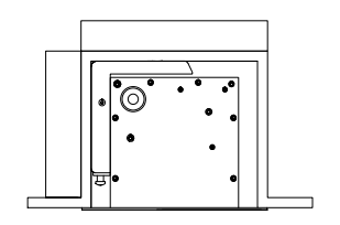
Suspended Bracket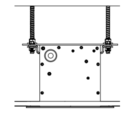
Flush Installation #
Measure Case & Cut Out Pocket #
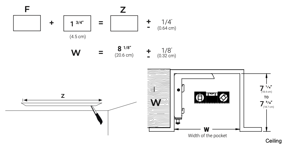
Measure the case length and record the measurement. If pre-constructing the pocket then refer to the screen builder for the F dimension for your particular size screen.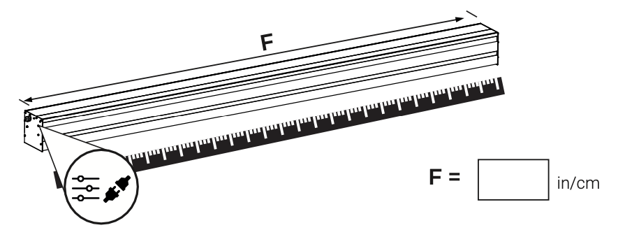
Calculate the pocket ceiling dimensions and prepare the ceiling cutout as described below.
Warning: It is highly recommended to provide a 6″ x 12″ access panel at the left end of the case and/or make sure the left end of the case can be accessed from inside the ceiling or attic.
Add End Flange & Remove Weight Bar Lock #
Line up the holes on the removable flanges with the holes in the end plates. Then install and hand tighten the flat head screws as shown.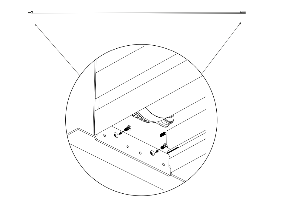
Mounting Flush L-Brackets #
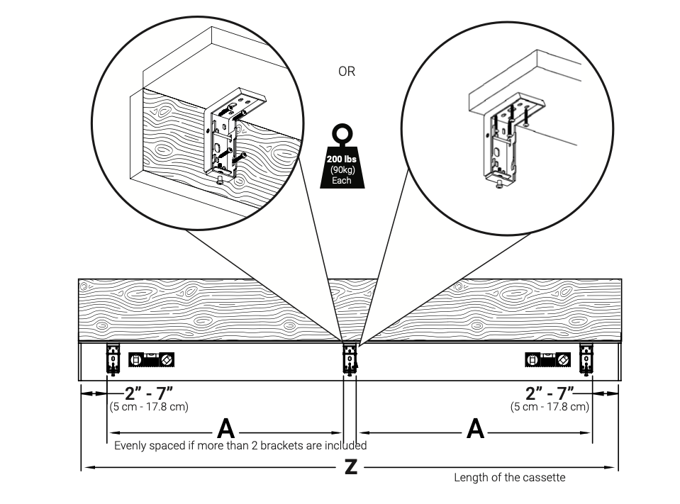
Mount the L brackets either to a vertical or horizontal structural support as shown. Make sure brackets are all along the same level line and plumb.
Mounting screws have been provided for mounting to wood structural supports only. If mounting to other substrate then installer must provide appropriate fasteners.
Warning: Each bracket must be able to hold 200lb load.
Hang Case on L-Brackets and Raise Up #
Make sure the hooks on the L brackets are adjusted down. Then raise the case up and hook the case into all the hooks on each bracket.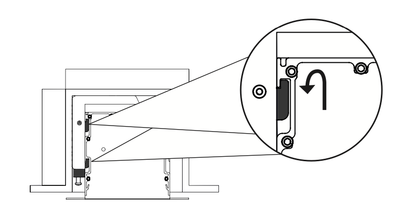
Tighten the screws in the L brackets to raise up the case until the end flanges touch the ceiling and the cassette is level.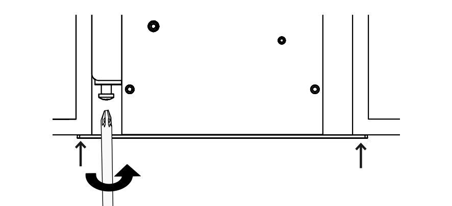
Mounting Flush Suspended Brackets #
Install minimum 3/8″ maximum 1/2″ threaded rod to structural members in the ceiling per the drawing below.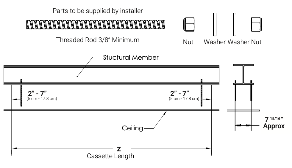
Install the suspended ceiling bracket kits onto the case as shown. Move the brackets to match the horizontal position of the threaded rods and then lock down with all 4 screws in each suspended ceiling bracket assembly.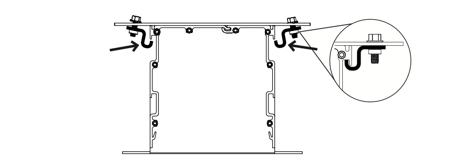
Hang Case on Suspended Brackets and Raise Up #
Raise the case up and guide the threaded rods through the holes in the suspended ceiling brackets. Secure with nuts and washers supplied by the installer.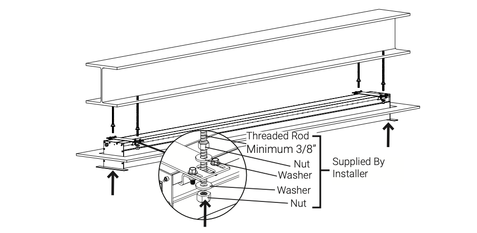
Use the nuts connected to the threaded rods to raise the case up until the end flanges touch the ceiling and cassette is level.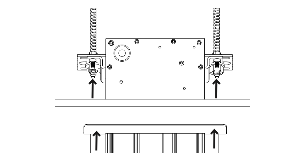
Flush Trim Installation #
Hook the larger front closure into the case opposite the weight bar and then rotate down to secure. Make sure the trim is hooked into the case along entire length before proceeding.
Warning: Please ensure weight bar screws are removed prior to screen operation.
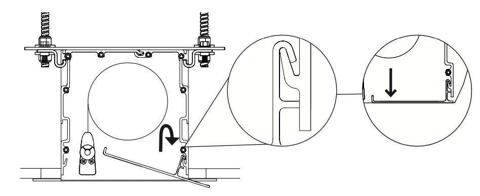
Hook the smaller back closure into the case on the side of the weight bar and then rotate down to secure. Make sure the trim is hooked into the case along entire length before proceeding.
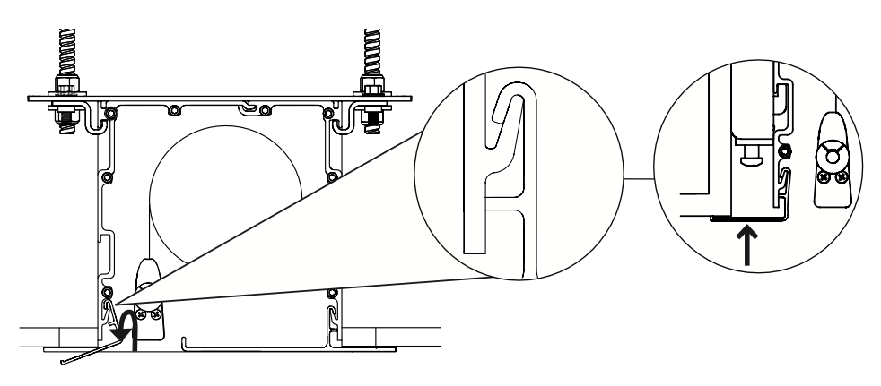
Flush Trim Locking #
Insert the bumpers into the holes in the endplates. Press the pin in the bumper until you feel a SNAP indicating the bumper is secured. Before proceeding make sure the bumpers are secured to the endplates. Do this at both ends of the screen. Snaps must be set in place correctly to ensure mechanical operation.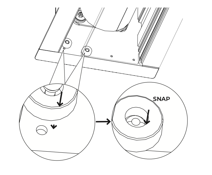
Remove the tagged Weight Bar Locks.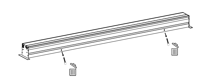
Adjusting Tab Tension #
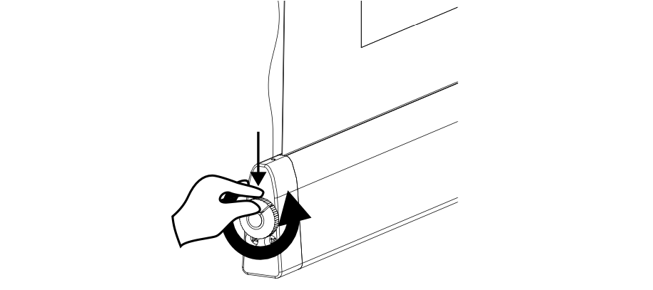
Loosen tension: Press in the button and turn knob counter clockwise until the string is loose.

Apply minimal tension: Turn the knob clockwise 2 to 4 clicks at a time until there is tension on the string. The strings should have minimal tension on them only.
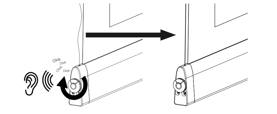
Warning: DO NOT OVER TIGHTEN TAB TENSION STRINGS: Tab tension strings will NOT flatten out wrinkles in the screen. The purpose of tab tensioning is to reduce viewing material edge curl. Over tightening the tab tension strings can result in damage to your screen material.
Line Level Voltage (AC) – Wiring #
Terminate the wires with the provided terminal block shown below.
Make sure an appropriate junction box or power receptacle is located within 5ft of the installation location.
Warning: Installer must follow all local electrical codes when connecting 110v AC power. Certified electrician is required to connect pigtail power.
110v AC/60 Hz: L (Black), N (White), Ground (Green) — Length: 12–14′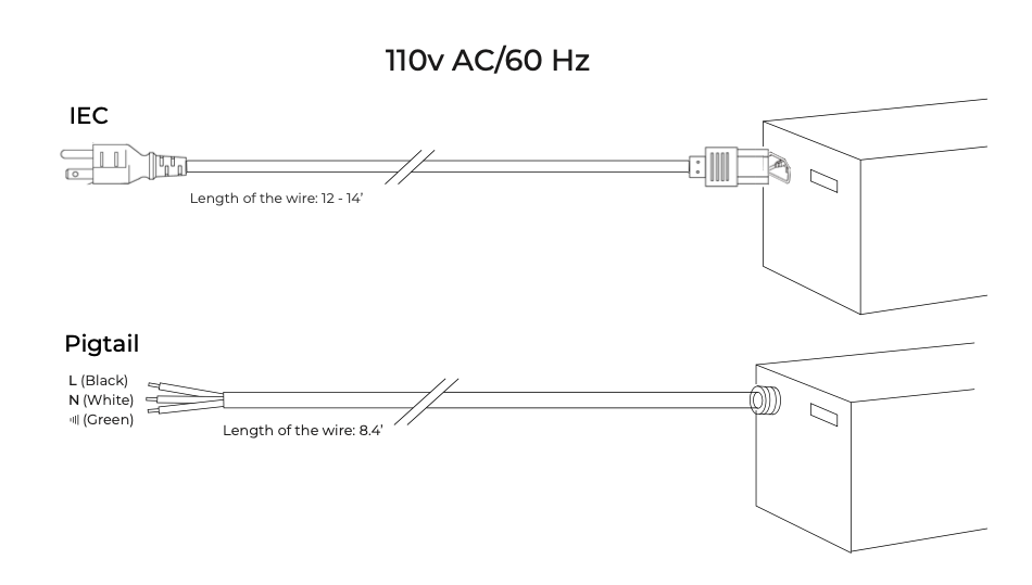
220v AC/50 Hz: L (Brown), N (Blue), Ground (Green/Yellow) — Length: 8’4″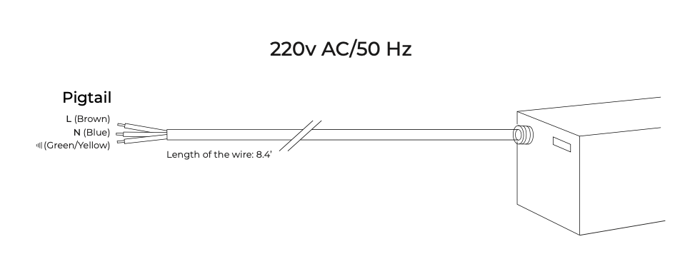
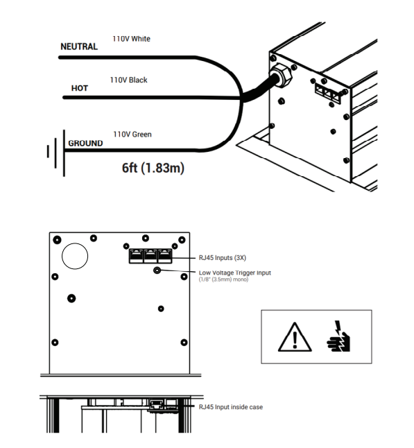
110v AC – DCT Motor #
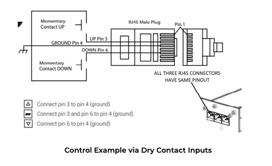
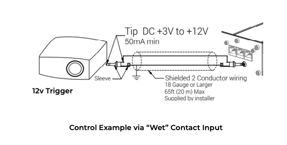
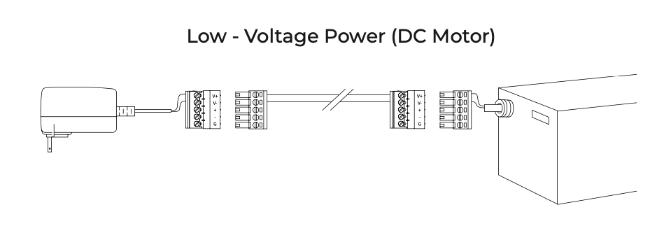
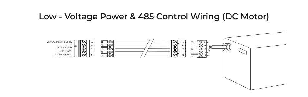
Low Voltage (DC) – Wiring #
DC Motor Wiring:
Power 24v DC – Red
Ground – Brown
RS485 (+) – White
RS485 (–) – Orange
Pin 1 to Pin 8 (with service loop)