
Before Proceeding #
WARNING: SI recommends conducting a visual inspection, to check the internal brackets, material roll, and electronics for any concealed shipping damage before proceeding with the screen installation.
For best results, read the instructions in their entirety before proceeding with assembly. Actions contrary to the instructions invalidate the warranty and may result in serious damage and/or injury.
Preparing for Installation: #
It is crucial that all installations are planned out carefully before specifying a screen order and assembly.
Before installation, Bracket/Mounting method and Assembly Installation method must be identified.
Do not use a knife to cut foam or wrapping, as this may damage the shade including, but not limited to, the cassette, fabric tube, and material roll.
The tube may shift within the cassette during shipping; open the cassette with care.
Unpacking the box – lay cassette, fabric tube, and material roll on a soft, clean surface during the installation process.
When removing from the box, ensure the assembly is kept horizontal to prevent damage.
Screen Innovations recommends METHOD 2 (removal of the material roll before installation) when installing the Solo 3 screen for better control and safety of the material inside.
When removing material from the cassette, use at least two people to lay material down on a clean, flat surface, such as a blanket or sheet.
When utilizing either method, especially METHOD 1, make certain there are enough installers/hoisting equipment to safely lift the cassette (and/or material) onto the brackets.
Brackets must be level and in-line with one another before attempting to lift cassette onto brackets. Use safe lifting and rigging techniques.
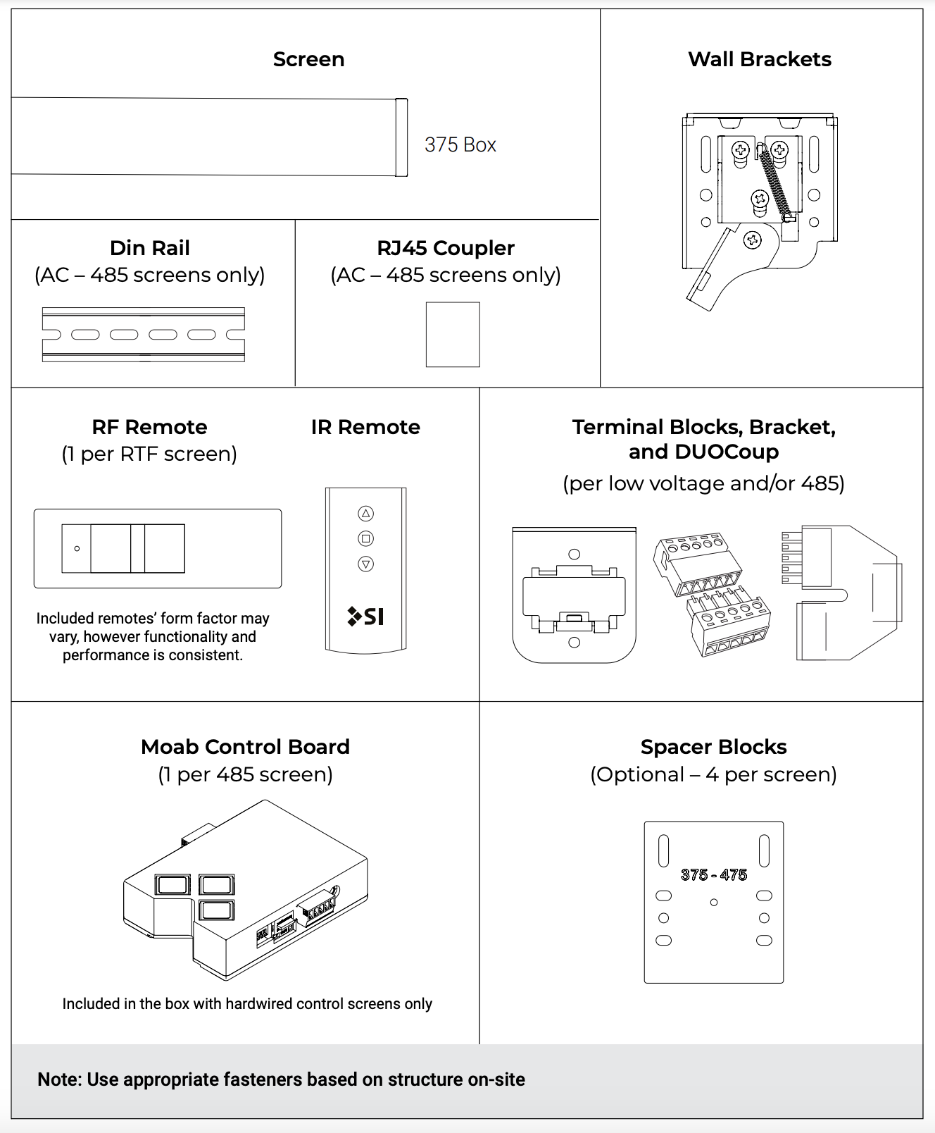
Parts in the Box #
Solo 3 Indoor 375 External #
Installation Steps #
375 External Mount Installation Guide #
Step 1: Low Voltage Terminations #
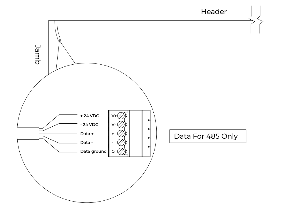
FOR LOW VOLTAGE SCREENS:
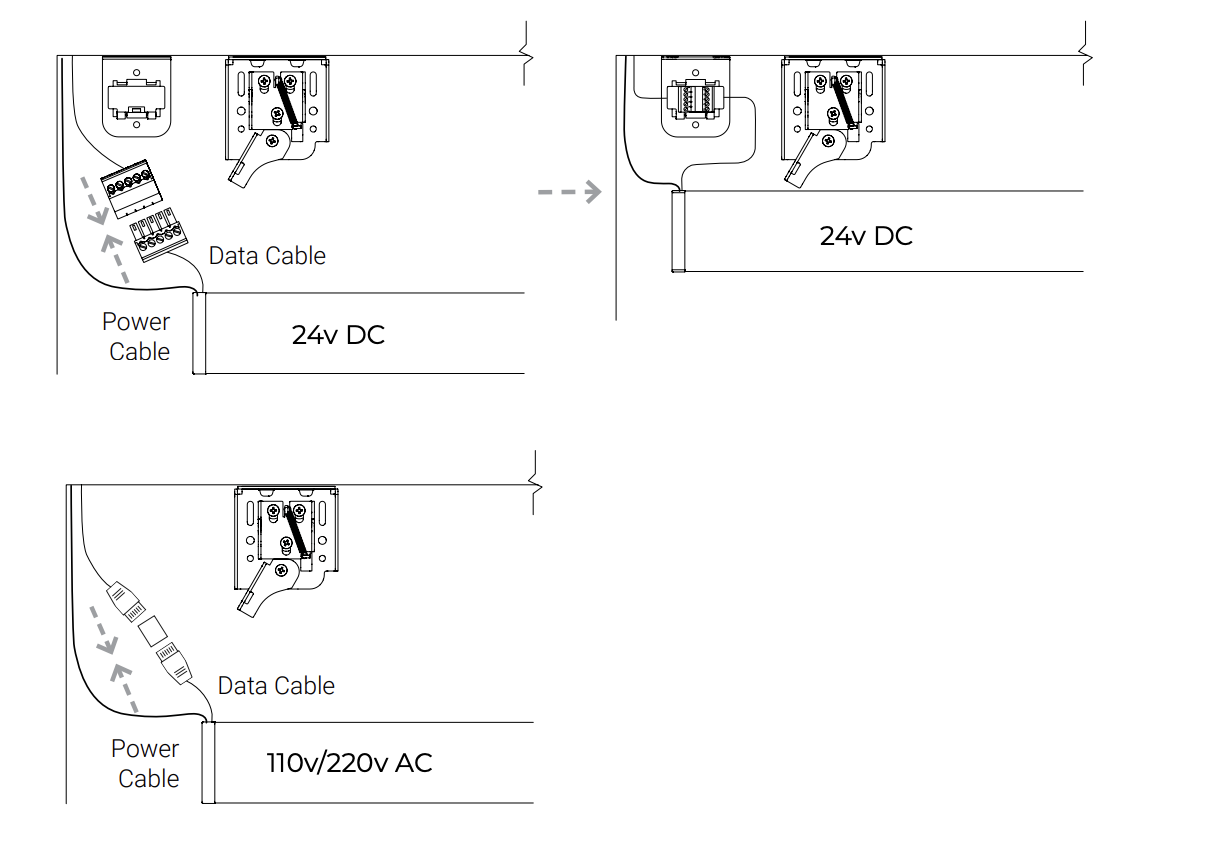
Terminate pre-wire with the supplied terminal block.
Step 2: Spacer Blocks (Optional) #
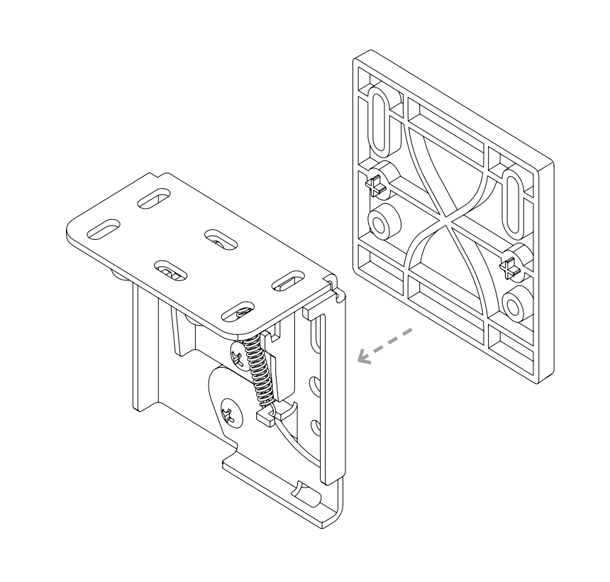
Used to clear an obstruction in the screen or screen material path. Before installing, connect spacer blocks to screen brackets.
Do not use more than four (4) spacer blocks per bracket
Step 3: Bracket Placement #
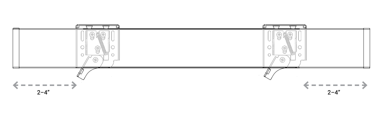
The recommended position for the box bracket is 2-4″ from the end caps.
Installing the wall brackets as close to the end of the cassette as possible ensures better stability of the screen.
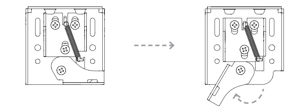
Step 4: Lever Position #
To install the screen, start with the wall bracket lever pointed down in the unlocked position.
Step 5: Terminations for LV 485 Motors with MOAB #
Ensure the terminal blocks are plugged in and installed in the brackets.
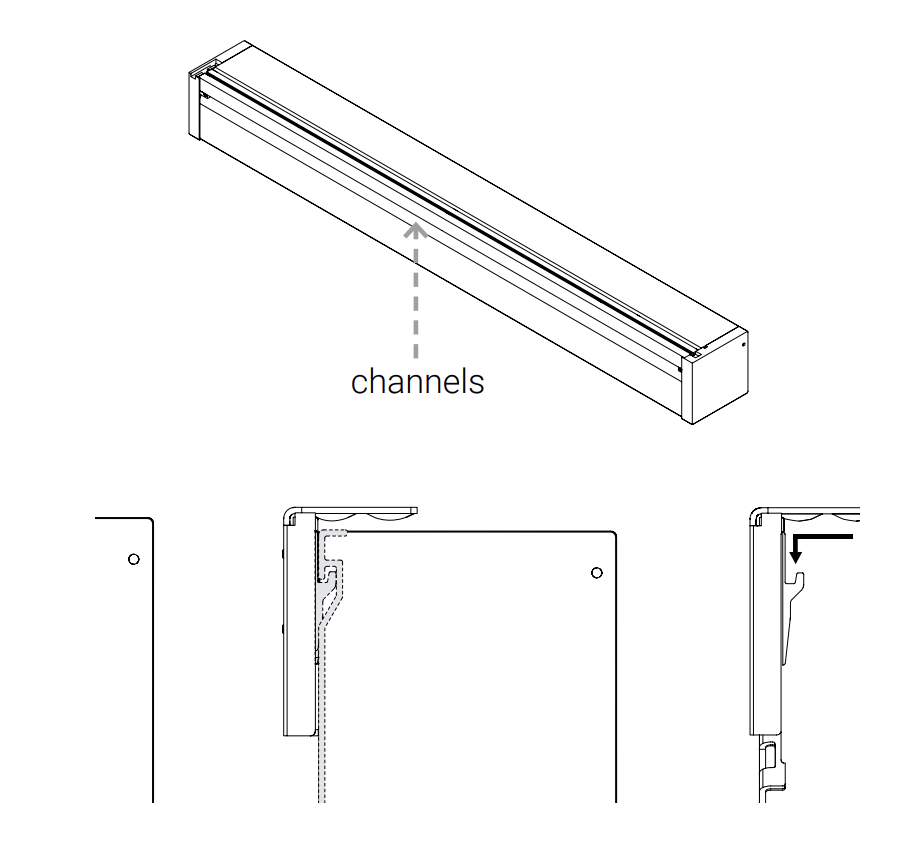
Step 6: Hanging the Screen #
Locating the channel running along the back of the screen, hook the channel onto the wall brackets.
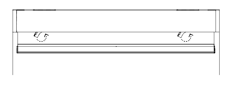
Step 7: Locking the Brackets #
Reaching under the cassette, move levers up into the locked position, keeping the screen secure.
Step 8: Removing the Weight Bar Shipping Brackets #
Remove the Secure tape.
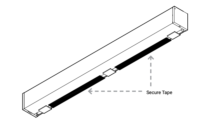
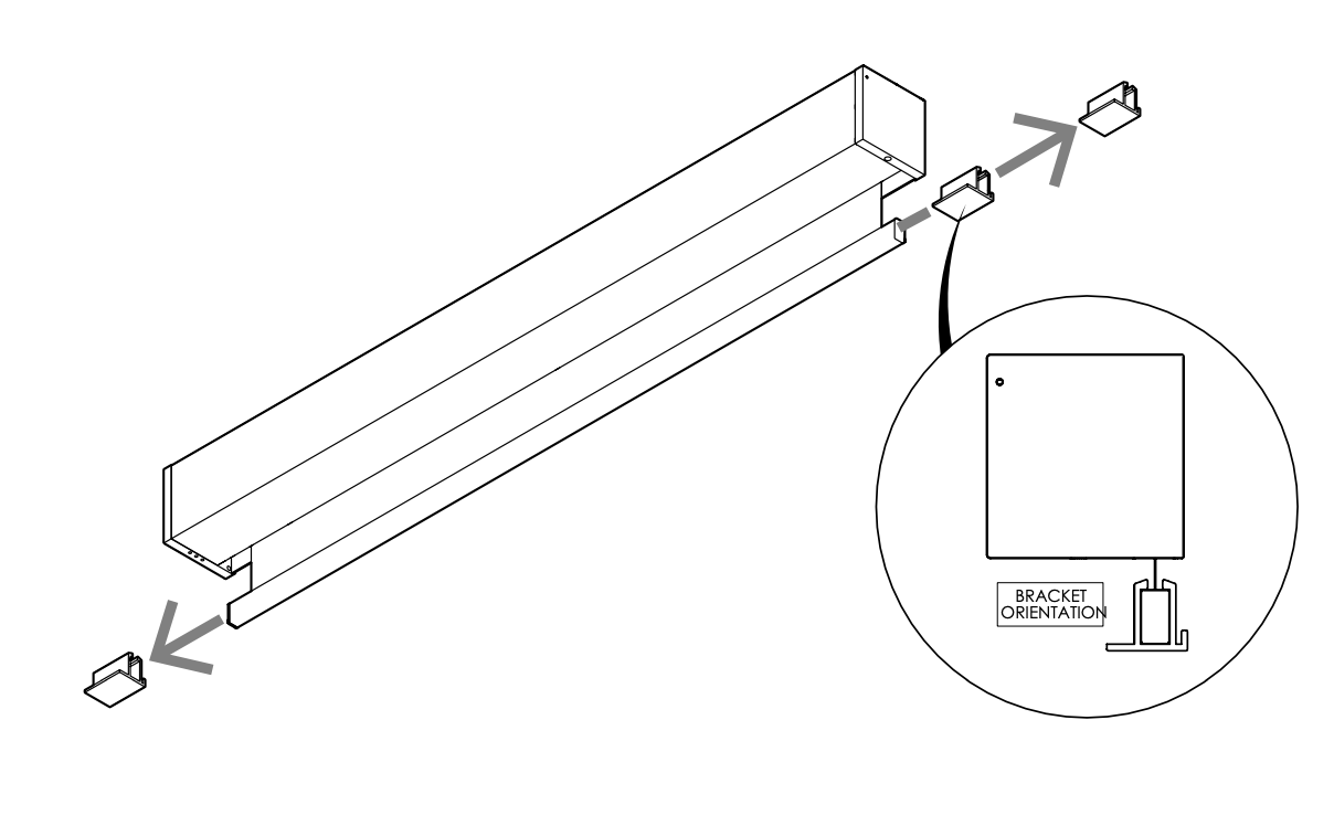
Lower the screen using the Moab. Now slide the brackets off the weight bar as shown.
Step 9: RTS Wireless or 485 Wiring #
Wiring – 485 Motor with MOAB #
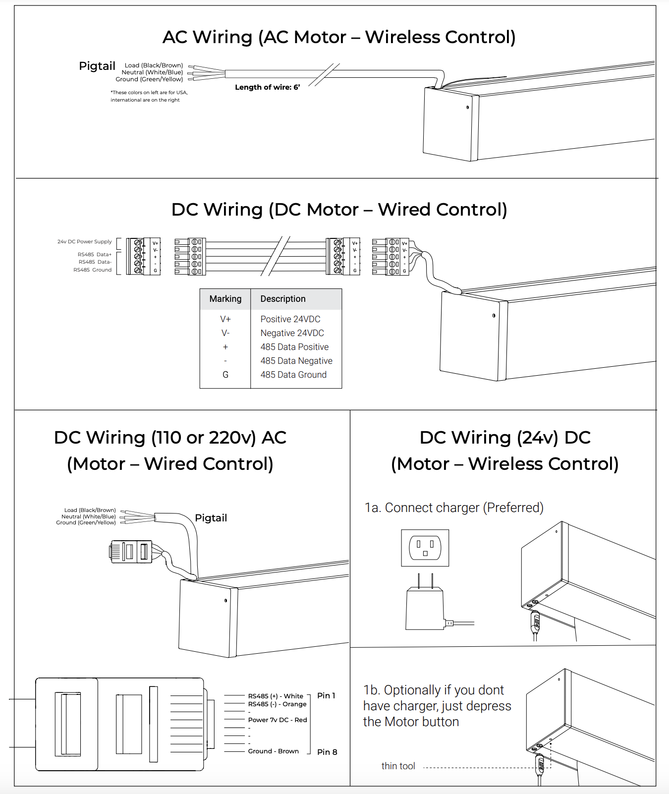
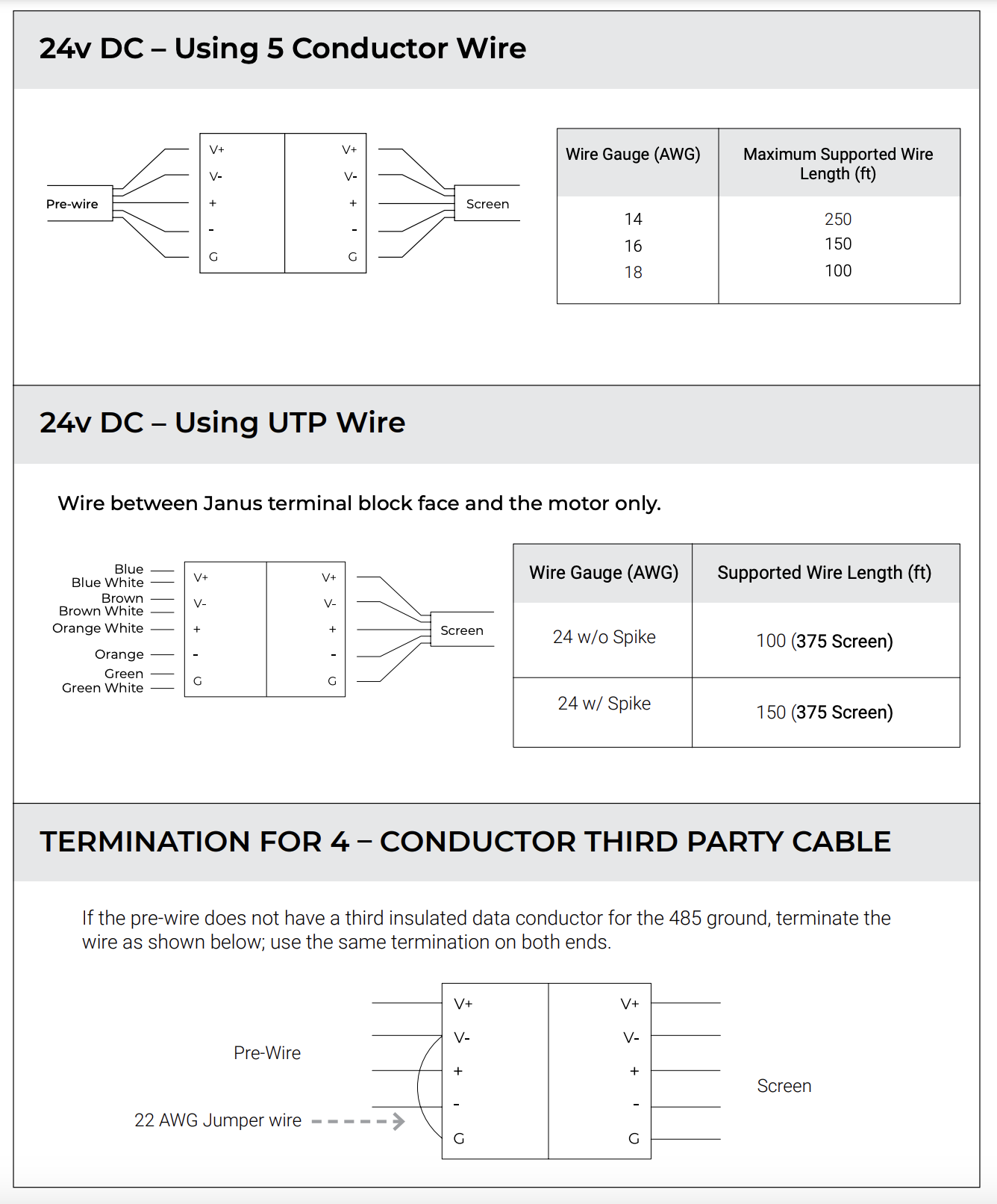
Step 10: Wiring – 485 Motor with MOAB #
If the screen is wired with wired communication or 485 control, it will include a motor control board, Moab.
This control board allows for setting limits and/or controlling the screen.
Typically, this board is located in the head end/equipment location.
See the wiring chart on page 11 to determine maximum wire length.
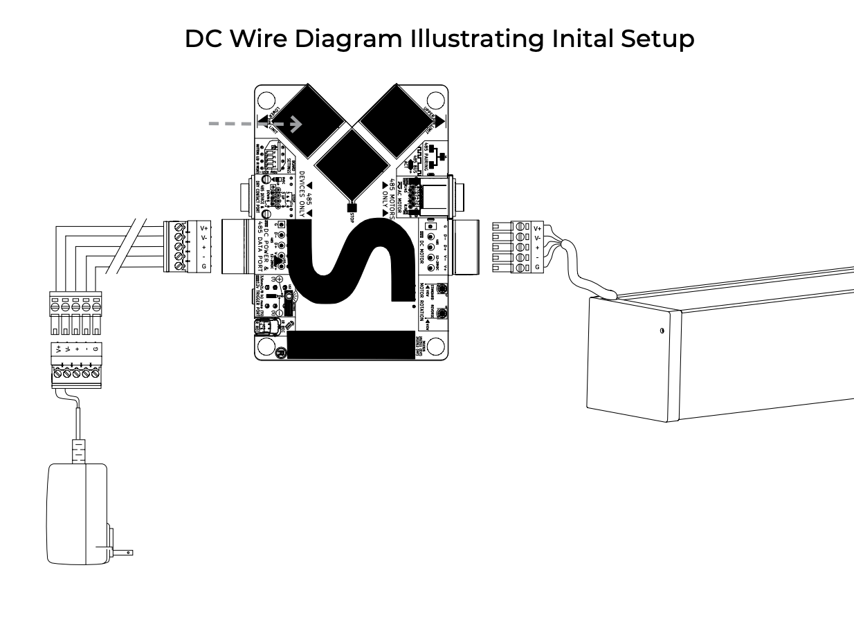
Step 11: Final Connections #
Upper and lower limits are already factory-set.
Once all connections are made including the power supply, you may now adjust the lower limits using the Moab control board.
Once all adjustments are made and finalized, the Moab may now be placed in a convenient location for the install.
Third party control such as Dry Contact closures, 12v Triggers, Serial Connections, and Infrared may now be integrated with Moab.
See the MOAB Setup & Integration section below for complete setup instructions.