
Required Tools for Installation #
Ladders, Lifts, or Scaffolding
Headlamp
Laser Level
4-6′ Level
Tape Measure
Screwdrivers, Sockets & Bit Set
Wiring Tools
Drill and Bits for wood, metal and masonry
Hex Key Set (Ball end recommended)
Miter Saw (Chop Saw), 7″ + blade (Best Practice: Blade rated for Aluminum)
Drop Cloth or Tarp
110v AC Wire Terminations (NEMA Plug or WAGO/Wire Nuts)
Multimeter
Eye Protection
Sharpie’s/Pencil
Variety of Shims
Painters Blue Tape
Optional Tools #
Countersink bit & Screws
Appropriate fasteners for: #
Brackets
Thru-bolting
U-Channel attachment
Track to U-Channel attachment
On-Site Checklist #
Open and inspect contents
If any visible damage, please photograph packaging, and damaged contents and report to Techsupport@screeninnovations.com
If anything is missing, confirm all boxes shipped and report to Techsupport@screeninnovations.com
If there are multiple boxes in the shipment, accessories will be overpacked in one of the boxes, identified with a sticker
Prep Jobsite for install
Remove shade and tracks from packaging (DO NOT use a blade)
Installation Steps #
Pocket Installation Overview #
For all recessed installations, U-channels must be installed prior to the installation of the track system. U-channels can and should be installed before the main shade is ordered to ensure proper coordination and fit.
It is critical to verify that both the tracks and the shade boxes can be installed securely, level, and plumb. Prior to installation, ensure that all necessary blocking or structural carpentry work has been completed to provide solid attachment points for the tracks and shades.
All electrical work must be completed in accordance with local electrical codes and regulations and performed by a licensed electrical professional.
When mounting the KAOS shade system, only use fasteners appropriate to the structural material of the building. Improper fastening can result in system failure or damage.
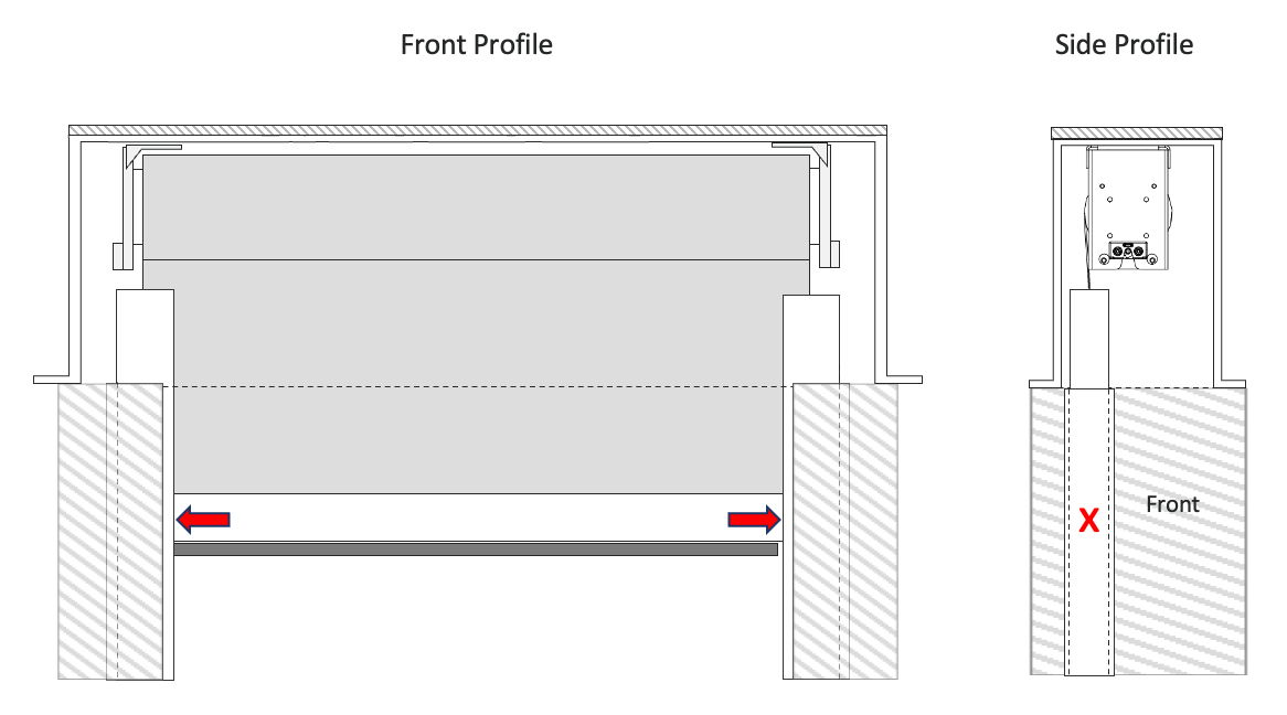
For optimal recessed installation, we recommend a pocket size of 8″ wide by 12″ high.
Warning: Failure to follow these guidelines may compromise the performance, safety, and aesthetics of the installation.
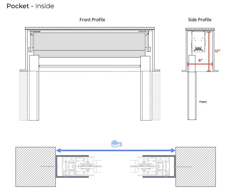
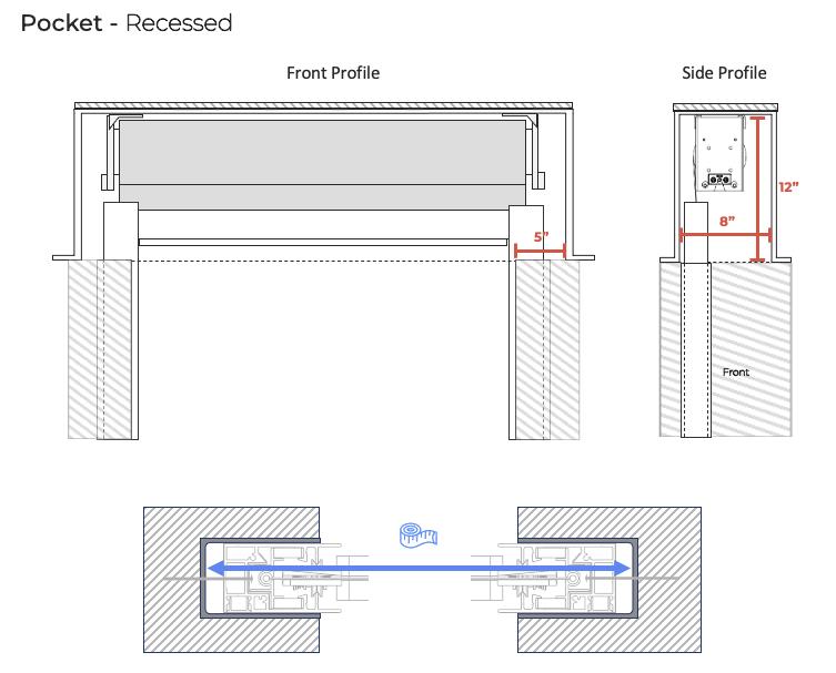
Step 1: Inspect Pocket #
Verify that the upper corners of the pocket are clear of any obstructions.
Confirm no interference with bracket placement or operation.
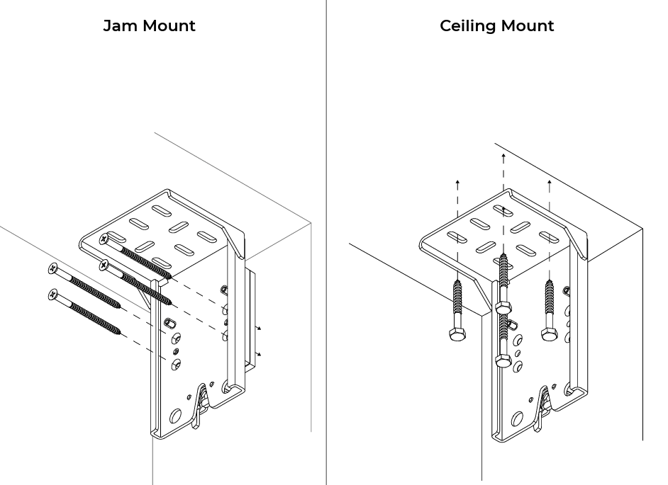
Step 2: Bracket Installation #
Position mounting brackets 3/4″ from the outside edge of the Tracks.
Reference the back plate of the mounting bracket for placement; do not use the latch system as a guide.
Use fasteners appropriate to the structure (concrete, metal, wood, etc.), rated to support the full weight of the KAOS Shade system.
Ensure brackets are installed securely, level, and properly aligned.
Step 3: Power Wire Preparation #
ELECTRICAL SAFETY WARNING
Installation must follow all local electrical codes when working with 110V AC power. Use a certified electrician when necessary. Ensure power is OFF before making any electrical connections.
Prepare the Power Wire
Make sure these wires are secured so that they will not be damaged during installation of the cassette.
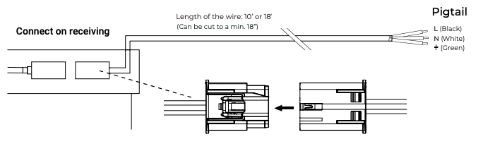
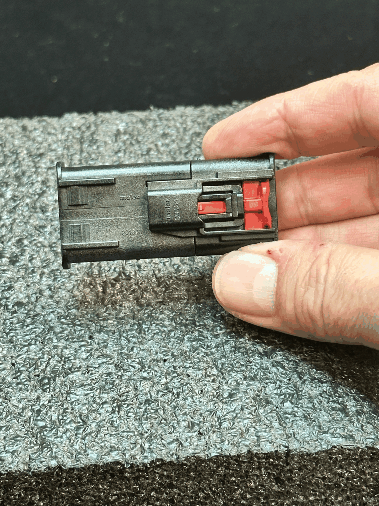
All KAOS shades have an internal disconnect and ships disconnected. Before running the shade, open the shade door and complete the connection.
To use the “Quick Connect” Slide the RED “Lock” away from the center – Press down on the BLACK part between the RED – While pressing Down, pull the connectors apart
Step 4: Installing the Fabric Roll #
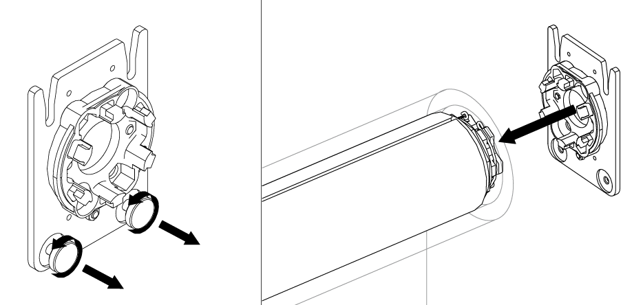
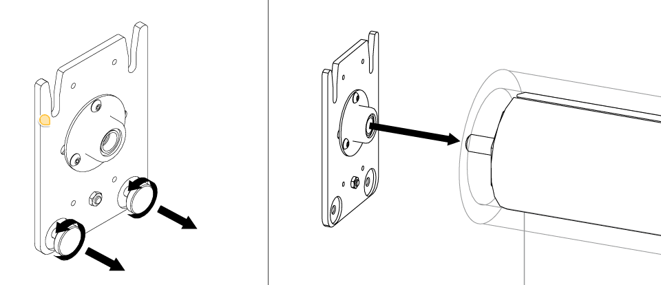
Remove Thumb Screws
Install Bracket Inserts
Push motor side bracket until it clicks securely into place. (Figure A)
Insert the Idler plate onto the Idler pin. (Figure B)
Identify the Motor and Idler side, and the correct roll orientation.
Position both sides under the cassette and push up simultaneously on the left and right sides.
A distinct “click” will confirm the shade is secured.
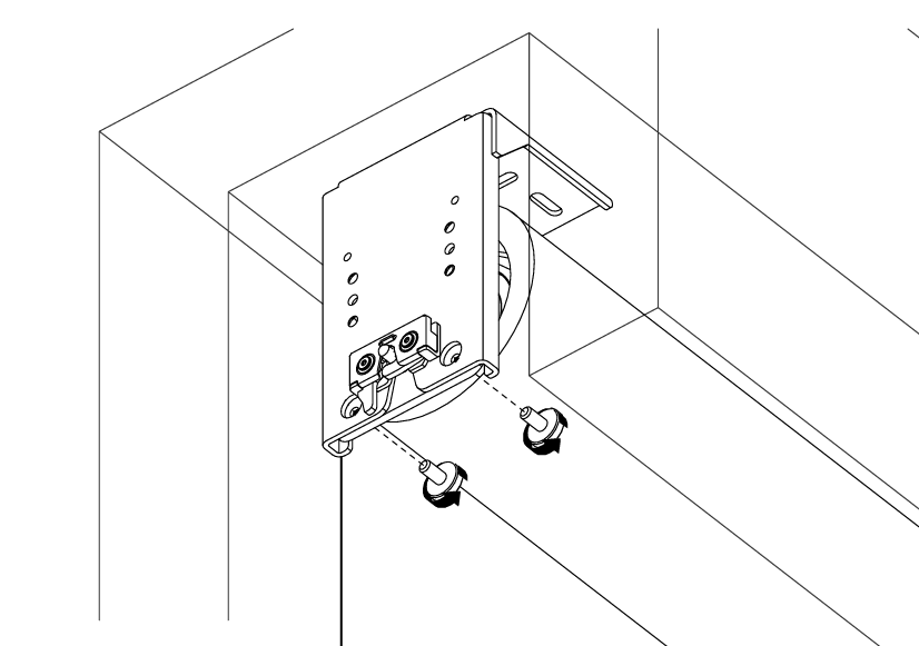
Secure the Thumb Screws (Figure C)
Tighten the thumb screws to securely lock the material roll in place on both ends.
Pre-check roll for Telescoping, if Keder is not stacked evenly on both sides, CLICK HERE for the instructions to correct this before continuing.
(Figure A)
(Figure B)
(Figure C)
Warning: The motorplate is secured to the motorhead with the C-clamp, the idler can slide off easily
Warning: Be sure the motor and its tube adaptor, and idler and its tube adaptor are fully seated into the tube before installing the roll into the cassette.
Step 5: Shades under 6′ Additional Weight Bar Assembly #
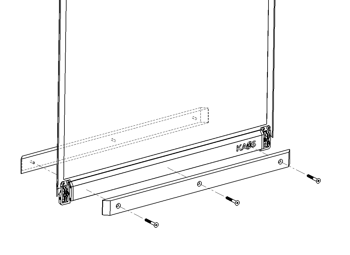
Lower the bottom edge of the shade until it is approximately 5 inches above the ground.
Align the front and rear steel bars with the three mounting holes on the hem bar.
Attach the front and rear steel bars to the hem bar.
The Rear external weight bar will be the ones with the holes all the way through.
Begin by securing one end of the steel bars with one of the three provided weight bar screws. Leave the screw slightly loose.
Secure the opposite end with another weight bar screw, also leaving it slightly loose.
Install the third screw in the center. Once all three screws are in place, tighten them securely
Step 6: Motor Setup #
Important: KAOS shades ship with remotes unpaired and no limits set. You must complete motor programming before continuing.
Best practice: Only have 1 shade powered up while programming
Step 7: Track Installation #
Select your track mounting type — surface-mounted or recessed:
Option A: Surface-Mounted Tracks #
Track Step A1: Measuring and Cutting #
Cutting the U-Channels: #
Measure the distance from the bottom of the Pocket Bracket to the floor.
Cut the bottom of the U-Channels.
Tracks are labeled Left and Right on the top sides. The top is indicated by the black “Keder Feeder” and the removable “Stopper.”
Cutting the Tracks: #
Measure from the bottom of the roll at the keder to the floor.
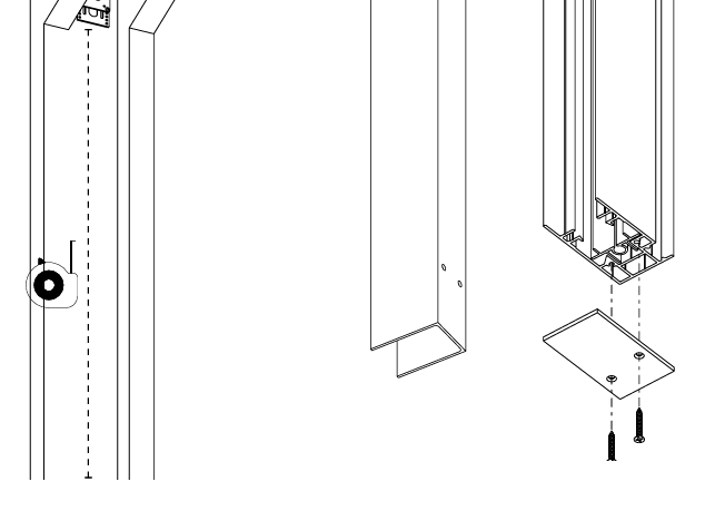
Subtract 2″ and cut from the bottom of the tracks.
Remove the bottom cap from each track.
Cut the track to length.
Warning: Always cut the bottom end of the track.
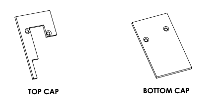
The top cap is 1/8″ thick and the bottom cap is 1/8″ thick — this guarantees the required ½” clearance between the cassette and the top of the U-Channel for the door to swing open.
Track Step A2: Track Positioning and Securing #
Warning: Track placement is critical for proper operation of the shade.
Insert the assembled Tracks into the U-Channels.
Lift the Weight Bar manually and feed the Keder into the “Keder Feeder” on the top of the tracks.
Ensure the ONYX Guides are correctly positioned and properly aligned with the track for smooth operation.
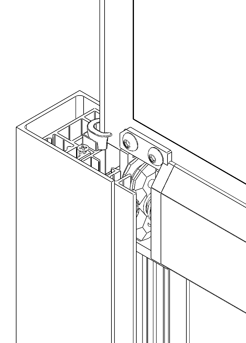
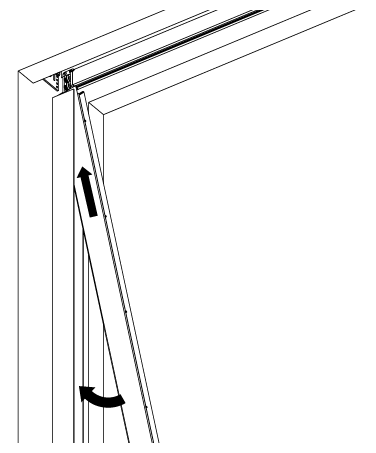
Move the shade to about 6″ below the pocket.
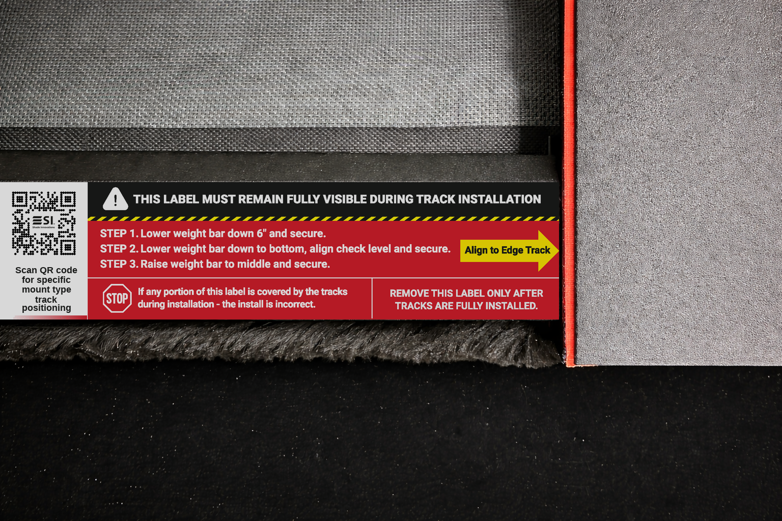
Adjust the tracks until the end of the weight bar and the edge of the tracks are aligned.
Tip: For a clean look use a countersink bit and screws.
Secure the tracks to the U-Channels at the same height as the weight bar.
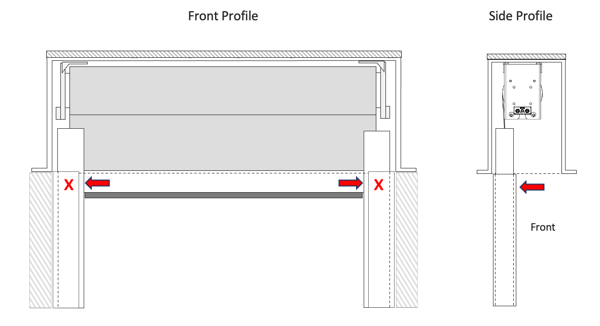
Use the supplied jig to align with the front of the tracks to mark the location, and drill the holes to screw the tracks to the U-Channels.
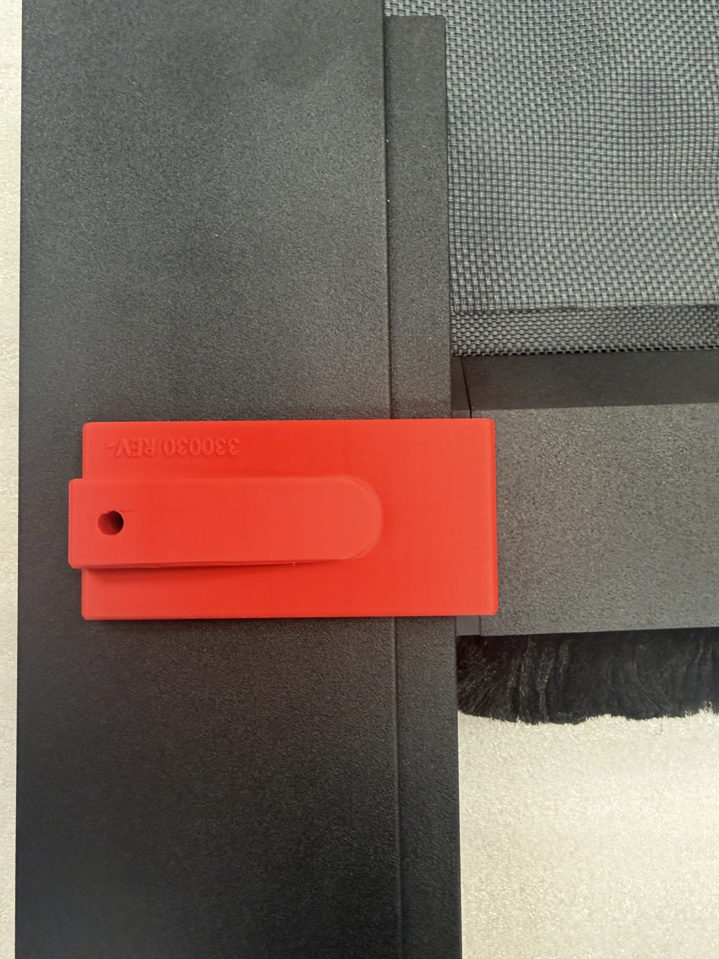
Secure the track to the U-channel using 1½” flanged screws.
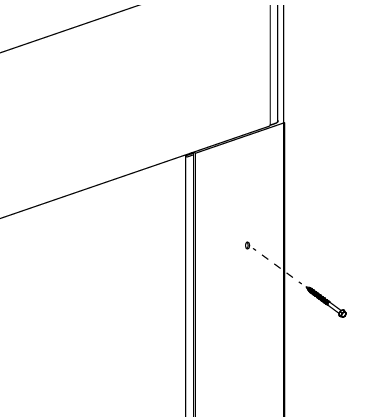
Move the shade to the bottom.
Adjust the tracks until the end of the weight bar and the edge of the tracks are aligned.
The tracks should be the same distance from the U-Channels on both sides.
VERIFY the track is plumb.
Secure the tracks to the U-Channels at the same height as the weight bar.
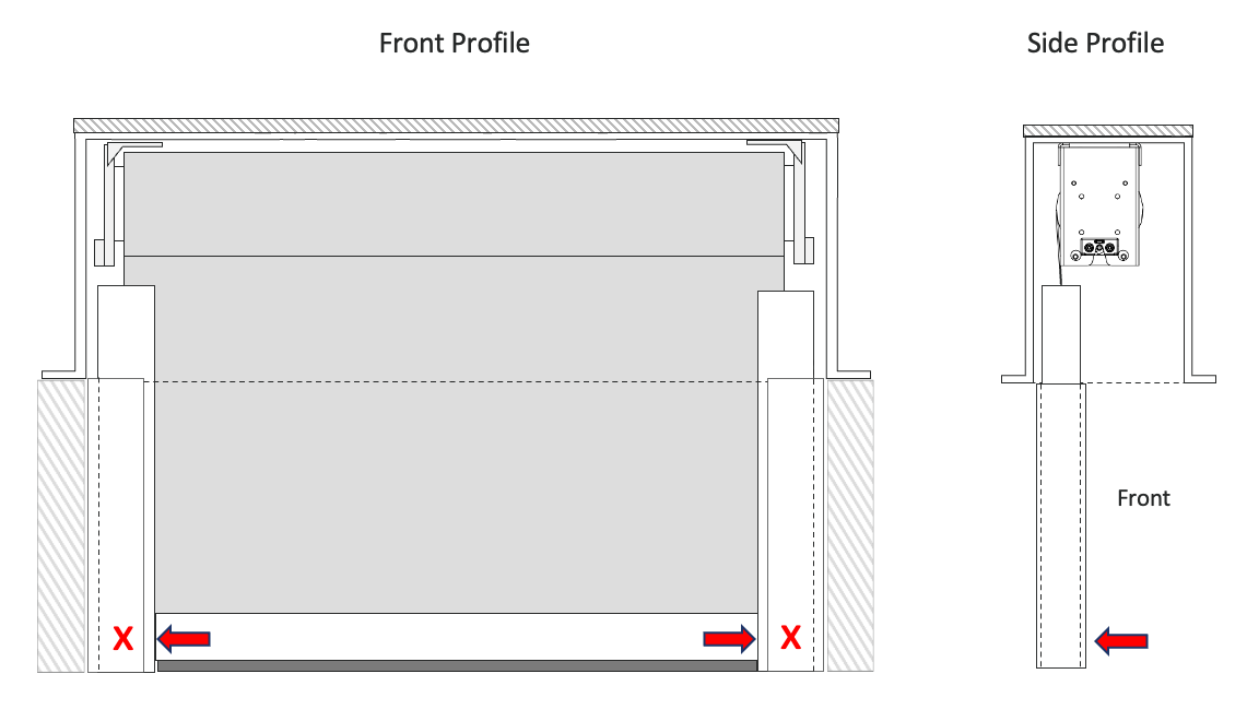
Move the shade to the middle.
VERIFY the tracks are still plumb.
Secure the tracks to the U-Channels at the same height as the weight bar.
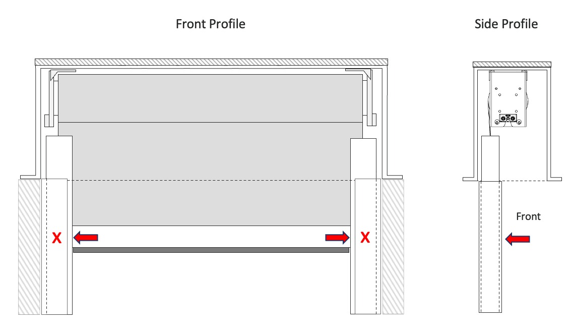
Using the jig, add more screws evenly spaced in between the top, middle, and bottom screws.
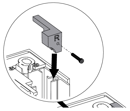
Install the wheel stopper as shown in the illustration to prevent the wheel system from coming off the tracks.
Warning: DO NOT SKIP INSTALLING THE WHEEL STOPPERS — Prevents the weight bar from coming out of the tracks.
Option B: Recessed Tracks #
Track Step B1: Measuring and Cutting #
Cutting the U-Channels: #
Measure the DISTANCE FROM THE BOTTOM OF THE POCKET TO THE FLOOR.
Cut the bottom of the U-Channels.
Tracks are labeled Left and Right on the top sides. The top is indicated by the black “Keder Feeder” and the removable “Stopper.”
Cutting the Tracks: #
Measure from the bottom of the roll at the keder to the floor.
Subtract 2″ and cut from the bottom of the tracks.
Remove the bottom cap from each track.
Cut the track to length.
Track Step B2: Installing U-Channels #
If recessed U-Channels are already installed, skip to “Track Positioning” below.
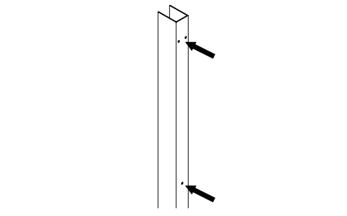
Pre-drill the U-channel: 2 holes each for TOP, MIDDLE, and BOTTOM; then 1 hole every 12 inches in spacing. Attach the U-Channel beneath the brackets.
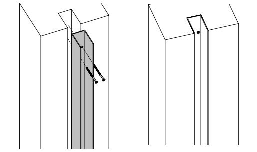
Secure both U-channels using the appropriate screws.
Track Step B3: Track Positioning #
Warning: Track placement is critical for proper operation of the shade.
Insert the assembled Tracks into the U-Channels.
Lift the Weight Bar manually and feed the Keder into the “Keder Feeder” on the top of the tracks.
Ensure the ONYX Guides are correctly positioned and properly aligned with the track for smooth operation.
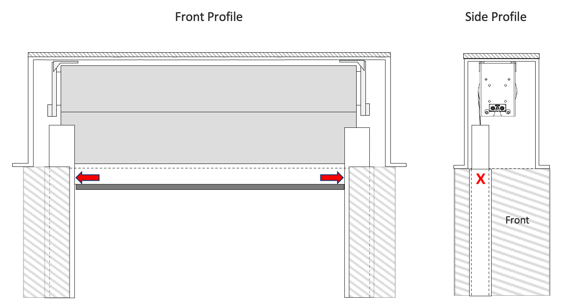
Move the shade to about 6″ below the pocket.
Adjust the tracks until the end of the weight bar and the edge of the tracks are aligned.
Do this on both tracks.
Mark the location of the tracks inside the U-Channel on both tracks.
Move the shade to the bottom.
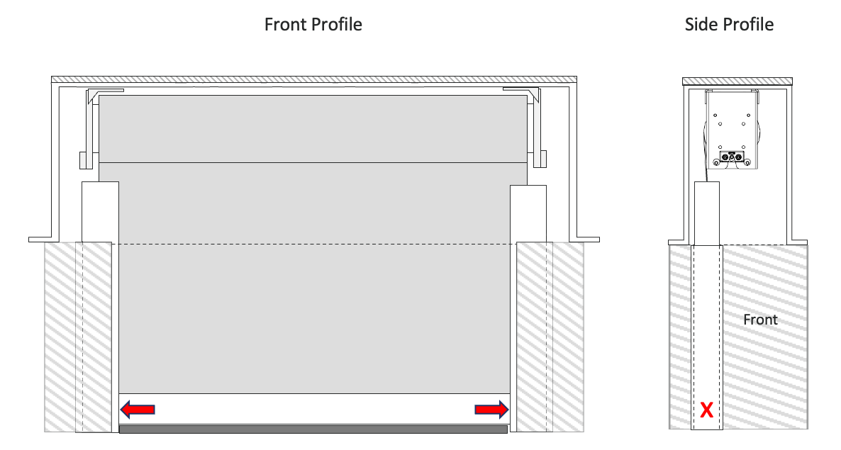
Adjust the tracks until the end of the weight bar and the edge of the tracks are aligned.
VERIFY the track is plumb.
Mark the location of the tracks inside the U-Channel on both tracks.
Move the shade to the middle.
VERIFY the tracks are still plumb.
Mark the location of the tracks inside the U-Channel on both tracks.
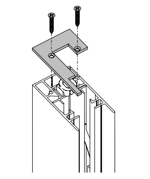
Track Step B4: Dis-assembling the Tracks #
Remove the top cap: unscrew the two securing screws.
Remove the bottom cap: unscrew the two securing screws.
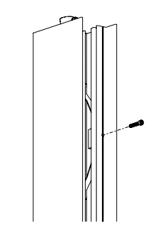
Remove the screws holding the spring clips along the front of the track.
Push down on the spring clip and rotate it outward to release it from the track.
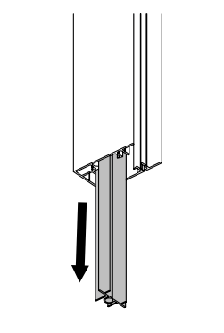
Pull out the track from the outer track.
Track Step B5: Installing the Tracks in the U-Channels #
Warning: Shims may be needed at the back of the track for leveling. (Shims are not provided.)
Using the marks made from the Track Positioning step, pre-drill holes to secure the track to the U-channel at the Top, Middle, and Bottom, and evenly spaced in between. Use the centerline inside the track as a guide.
Start with the Top mark, then Bottom (VERIFY it is plumb), then center. Shim as necessary.
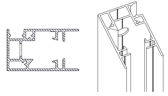
Track Step B6: Re-assembling the Tracks #
Insert the track at a slight angle.
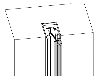
Once the track is inside the outer track, rotate it to position it correctly.
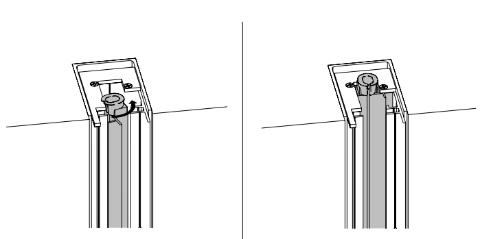
To reinstall the spring clip, push it between the track and the outer track, then rotate it into place.
Ensure the hole in the spring clip aligns with the holes in the outer track.
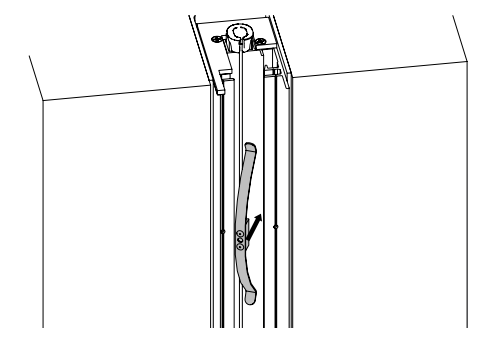
Reattach the spring clips and secure them with the screws removed earlier.
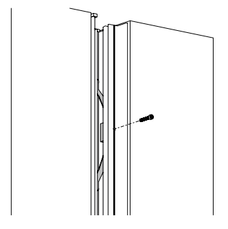
Reattach the top and bottom caps and secure them with the two provided screws.
Lift up the weight bar and guide the keder into the keder-feeder and align the guide wheels into the track.
Install the wheel stopper as shown in the illustration to prevent the wheel system from coming off the tracks.
Warning: DO NOT SKIP INSTALLING THE WHEEL STOPPERS — Prevents the weight bar from coming out of the tracks.
If experiencing telescoping, unlevel weight bar, or binding, the tracks will need to be adjusted — requiring disassembly and reassembly of the tracks.
Step 8: Fine Tuning #
Fine tune the upper and lower limits.
Refer to the Motor Programming Guide.
Check the shade for level and the tracks for plumb to ensure the fabric is rolling without telescoping or binding.
Next Step: Program Your Motor #
Once the shade is installed, program the motor using the full guide for your motor type:
SI KAOS Motor Programming Guide (blue label on motor head / SI remote)
Somfy Motor Programming Guide (yellow/silver Somfy branding)
Not sure which motor you have? Both guides start with a motor identification section.
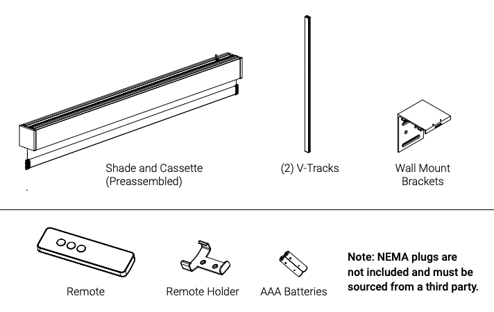
Parts in the Box #
Parts will vary based on your specific order configuration.
Related KAOS Guides #
Related Videos #
KAOS Track Disassembly
Swapping over to Onyx
Adding KAOS to Bond