
Overview #
This guide provides the knowledge needed to design reliable wireless shade systems. Proper planning of the entire wireless environment before installation leads to successful first-visit deployments, satisfied customers, and fewer callbacks.
The Screen Innovations Eco-System uses Zigbee wireless technology to control motorized shades. Zigbee operates in the 2.4 GHz frequency band, which is shared by Wi-Fi, Bluetooth, and many other wireless devices found in modern homes and buildings.
Successful wireless shade installations require understanding this shared spectrum and planning all wireless systems together. This guide teaches you how to:
Identify and document all wireless devices in the environment
Coordinate wireless systems to minimize interference and congestion
Design mesh networks with proper coverage and redundancy
Select channels that coexist with existing systems
Adapt your approach for residential, luxury, and commercial environments
Verify your installation meets performance standards
2.4 GHz
Operating Frequency
15-20 ft
Max Router Spacing
2-3 hops
Maximum Hop Count
50 ft
Max RS-232 Cable Length
First Visit Success
Understanding the Spectrum
Environment Assessment
Deployment Environments
New Construction
Retrofit Projects
First Visit Success #
The goal of every installation should be to complete the job successfully on the first visit. Callbacks are expensive, frustrate customers, and damage your reputation. Proper planning is the key to first-visit success.
The Three Principles of First Visit Success
1
Know the Environment #
Document all wireless devices before you arrive. Understand the Wi-Fi setup, identify other Zigbee systems, and note potential interference sources. You cannot design a reliable system without knowing what else shares the spectrum.
2
Plan All Systems Together #
Coordinate with IT, AV integrators, and electricians during the design phase. When all 2.4 GHz systems are planned together, you can allocate channels, position access points, and place Zigbee devices to minimize congestion and maximize reliability.
3
Design for Redundancy #
Plan mesh coverage so every shade has multiple paths back to the coordinator. Carry extra routers for field adjustments. A well-designed mesh self-heals when conditions change.
Questions to Ask Before Every Project #
Gathering this information during the quoting and planning phase prevents surprises during installation.
About the Building #
What is the square footage and number of floors?
What are the wall materials? (drywall, plaster, brick, concrete)
Is this new construction, retrofit, or remodel?
Where is the AV equipment located?
Can wiring be run to shade locations?
About the Wireless Environment #
What type of Wi-Fi system is installed? (consumer mesh, enterprise, carrier-provided)
How many Wi-Fi access points are there?
Are there other smart home systems? (Philips Hue, Control4, Savant, Crestron, SmartThings)
Is there an IT department or network administrator to coordinate with?
Are there wireless AV devices like wireless HDMI transmitters?
About the Shade Installation #
How many shades total?
What motor types are specified? (Low Voltage, WireFree, 485)
Where will the TRO.Y be located?
Can the Helen Coordinator be placed centrally, or must it be in an equipment closet?
Common Reasons for Callbacks #
Understanding why callbacks happen helps you avoid them. Most callback issues are preventable with proper planning.
Callback Reason | Prevention |
|---|---|
Shades intermittently unresponsive | Proper router coverage, channel coordination with Wi-Fi |
Shades work initially but fail later | Central coordinator placement, adequate hop count planning |
Some shades work, others do not | Sufficient routers to extend range, verify SILQ values |
Interference from new devices | Customer education, proper channel selection away from Wi-Fi |
System conflicts with other Zigbee | Document and coordinate channels with existing systems |
Understanding the 2.4 GHz Spectrum #
The 2.4 GHz frequency band is one of the most crowded portions of the wireless spectrum. Understanding what devices operate in this band and how they interact is fundamental to designing reliable wireless systems.
Why 2.4 GHz Is Crowded #
The 2.4 GHz band (2400-2483.5 MHz) is designated as an ISM (Industrial, Scientific, Medical) band, which means devices can operate in it without requiring individual licenses. This has led to widespread adoption by consumer and commercial wireless technologies.
Technologies That Share 2.4 GHz #
Wi-Fi (802.11b/g/n/ax) - Primary use in most buildings
Zigbee (802.15.4) - Smart home devices, shades, lighting
Bluetooth and BLE - Audio devices, wearables, keyboards, mice
Thread - Newer smart home protocol
Z-Wave (some regions) - Home automation
Proprietary wireless - Baby monitors, wireless HDMI, gaming peripherals
Microwave ovens - Generate interference when operating
Key Insight
Unlike licensed spectrum where specific frequencies are assigned to specific users, everyone in the 2.4 GHz band must coexist. Success depends on planning and coordination, not just signal strength.
How Wi-Fi and Zigbee Share the Spectrum #
Wi-Fi and Zigbee both operate in the 2.4 GHz band but use different channel widths and power levels. Understanding this relationship is essential for channel planning.
Wi-Fi Characteristics #
Uses 20 MHz or 40 MHz wide channels
Higher transmit power than Zigbee
Three non-overlapping channels: 1, 6, and 11
Can overwhelm Zigbee signals when on the same frequency
Zigbee Characteristics #
Uses 2 MHz wide channels (much narrower than Wi-Fi)
Lower transmit power than Wi-Fi
16 channels available (11-26)
Must avoid frequencies where Wi-Fi is active
Channel Overlap Reference #
Wi-Fi Channel | Center Frequency | Zigbee Channels Affected |
|---|---|---|
Channel 1 | 2412 MHz | 11, 12, 13, 14 |
Channel 6 | 2437 MHz | 15, 16, 17, 18, 19, 20 |
Channel 11 | 2462 MHz | 21, 22, 23, 24 |
Above Wi-Fi | 2475-2480 MHz | 25, 26 (Best for Zigbee) |
Recommendation
Zigbee Channel 25 operates above typical Wi-Fi traffic and is the recommended default for Helen systems. This channel provides the best coexistence with most Wi-Fi deployments.
Other Interference Sources #
Beyond Wi-Fi, several other devices can cause interference in the 2.4 GHz band. Identifying these during site assessment helps you plan around them.
Interference Source | Characteristics | Impact on Zigbee | Mitigation |
|---|---|---|---|
Microwave Ovens | Broadband interference while operating | Severe (temporary) | Place coordinator and routers 6+ feet away from kitchen |
Wireless HDMI | Continuous high-power transmission | High | Identify in AV racks; recommend wired alternatives |
2.4 GHz Baby Monitors | Analog video transmission | High | Recommend DECT 6.0 monitors (1.9 GHz) |
Bluetooth Devices | Frequency hopping, low power | Moderate | Generally tolerable; note heavy-use areas |
USB 3.0 Devices | Unintentional RF emissions | Moderate | Keep coordinator away from computers and hubs |
Gaming Peripherals | Proprietary 2.4 GHz protocols | Moderate | Note gaming areas; usually localized |
Wireless Security Cameras | Often 2.4 GHz Wi-Fi based | Moderate | Include in Wi-Fi channel planning |
Wireless Environment Assessment #
Site Survey Process #
A thorough site survey identifies all devices and conditions that affect wireless performance. This survey should be completed before finalizing the system design.
Step 1: Document the Wi-Fi Infrastructure #
Identify Access Points
Count the number of Wi-Fi access points and note their locations. Determine if this is a consumer mesh system, enterprise deployment, or carrier-provided equipment.
Consumer mesh (eero, Google Wifi, Orbi): Typically auto-selects channels
Enterprise (UniFi, Meraki, Ruckus): Usually managed with fixed channels
Carrier-provided: Often difficult to configure
Determine Channel Usage
Use a Wi-Fi analyzer app to identify which 2.4 GHz channels are in use. Note whether channels are set manually or automatically.
Step 2: Identify Other Zigbee Systems #
Ask the homeowner or building manager about existing smart home systems. Common Zigbee systems include:
System | Common Default Channel | Notes |
|---|---|---|
Philips Hue | 11, 15, 20, or 25 | Can be changed in Hue app settings |
Samsung SmartThings | Varies | Check hub settings |
Amazon Echo (Zigbee models) | 20 | 4th gen and Echo Plus have Zigbee |
Control4 | Varies by installation | Coordinate with Control4 dealer |
Crestron Home | Varies | Check system settings |
Savant | Varies | Coordinate with Savant dealer |
Hubitat / Home Assistant | Varies | User-configurable |
Important
Each Zigbee system on site should use a different channel. Document existing channel assignments and plan the Helen system to avoid conflicts.
Step 3: Note Potential Interference Sources #
Walk through the building and identify devices that could cause interference:
Location of microwave ovens relative to planned Zigbee devices
Wireless HDMI transmitters in AV racks
Baby monitors or similar analog wireless devices
Areas with heavy Bluetooth use (home office, gaming room)
USB 3.0 hubs near planned coordinator location
Step 4: Assess Building Construction #
Building materials significantly affect wireless signal propagation:
Drywall: Minimal signal loss
Plaster with metal lath: Moderate signal loss
Brick or concrete: Significant signal loss
Metal studs or foil-backed insulation: High signal loss
Low-E glass: Can block or reflect signals
Concrete floors between levels: Significant signal loss
Assessment Tools #
Professional Tools #
Wi-Spy + Chanalyzer
USB spectrum analyzer that visualizes the complete 2.4 GHz environment. Shows Wi-Fi networks, non-Wi-Fi interference, and identifies clear spectrum for Zigbee. Creates documentation suitable for commercial projects and IT coordination.
Recommended for: Luxury residential and commercial projects where detailed documentation adds value.
Basic Tools #
Wi-Fi Analyzer Apps
Mobile apps that show Wi-Fi networks and their channels. Available for iOS and Android. Sufficient for identifying Wi-Fi channel usage but cannot detect non-Wi-Fi interference.
Recommended for: Standard residential assessments.
Site Survey Checklist
A printed or digital checklist ensures you capture all necessary information. Document device locations, channel assignments, and building characteristics for reference during design and future troubleshooting.
Coordinating with Other Trades #
On larger projects, multiple trades install wireless systems. Coordinating during the design phase prevents conflicts and optimizes spectrum usage.
Coordination Opportunities #
IT / Networking: Agree on Wi-Fi channel assignments; request manual 2.4 GHz channel control
AV Integrator: Identify wireless HDMI usage; recommend wired alternatives where possible
Lighting Control: Coordinate Zigbee channel if using Hue, Lutron, or other Zigbee lighting
Security: Note wireless camera locations and frequencies
Electrician: Plan power locations for Zigbee routers if using smart plugs
Best Practice
Request a coordination meeting during the design phase. When all wireless systems are planned together, everyone benefits from reduced interference and improved reliability.
Zigbee Mesh Fundamentals #
Device Roles in the Mesh Network
Zigbee mesh network consists of three device types, each with a specific role:
Coordinator (TRO.Y 2 + Helen)
The coordinator is the central hub of the Zigbee network. There is exactly one coordinator per system. It manages the network, assigns addresses, and routes all communication.
Must be centrally placed for optimal coverage
RS-232 connection between TRO.Y and Helen must not exceed 50 feet
Keep away from Wi-Fi access points, metal enclosures, and interference sources
Routers
Routers are mains-powered devices that relay signals and extend mesh coverage. They are essential for reaching shades that cannot communicate directly with the coordinator.
Low Voltage Zigbee motors: Built-in routing when constantly powered
Zigbee smart plugs: Easy to deploy in existing outlets
Dedicated Zigbee routers: POE-powered options available
End Devices
End devices are battery-powered Zigbee shades (WireFree motors). They communicate with the nearest router but do NOT relay signals to other devices. They sleep most of the time to conserve battery.
Critical Design Point
WireFree (battery) shades cannot relay signals. If your installation uses mostly WireFree shades, you must add dedicated routers to maintain mesh coverage.
How Mesh Networking Works #
In a mesh network, messages can travel through multiple routers to reach their destination. This provides flexibility and redundancy compared to direct point-to-point communication.
Message Routing #
When the coordinator sends a command to a shade:
The coordinator transmits the message
If the shade is nearby, it receives the message directly (1 hop)
If the shade is far away, a router receives and retransmits the message
The message may pass through multiple routers (multiple hops) to reach the shade
Hop Count #
Each router-to-router or coordinator-to-router transmission is called a "hop." More hops mean:
Longer latency (slower response)
More opportunities for signal loss
Increased chance of communication failure
Maximum Hop Count
Every shade should be within 2-3 hops of the coordinator. Exceeding 3 hops significantly increases the risk of communication problems.
Self-Healing Behavior #
Zigbee networks are "self-healing" meaning that if one route fails, devices automatically find alternative paths. This only works when:
Multiple routers exist in the mesh
Routers have overlapping coverage areas
Devices are within range of more than one router
Design Principle
Design for redundancy. Every shade should have at least 2 potential paths back to the coordinator. This ensures the mesh can self-heal if one router becomes unavailable or a path is temporarily blocked.
Channel Planning #
Channel Selection Strategy
Proper channel selection ensures the Zigbee network coexists with Wi-Fi and other systems. Follow this process:
Step 1: Identify Wi-Fi Channel Usage #
Use a Wi-Fi analyzer to determine which 2.4 GHz Wi-Fi channels are in use. Note whether channels are manually set or automatic.
Step 2: Check for Other Zigbee Systems #
If other Zigbee systems exist (Hue, SmartThings, Control4, etc.), identify their channel assignments. Each Zigbee system should use a different channel.
Step 3: Select the Clearest Spectrum #
Zigbee Channel | When to Use |
|---|---|
Channel 25 (Recommended) | Best choice in most situations. Operates above typical Wi-Fi traffic. |
Channel 26 | Alternative to 25 if another Zigbee system is using 25. |
Channel 15 | Use if Wi-Fi avoids channel 6 and Zigbee channel 25 is occupied. |
Channel 11 | Use only if Wi-Fi channel 1 is not in use. |
Consumer Mesh Wi-Fi Warning
Consumer mesh Wi-Fi systems (eero, Google Wifi, Orbi) often use automatic channel selection that can change over time. For critical installations, recommend Wi-Fi systems with manual 2.4 GHz channel control, or plan for the worst-case channel scenario.
Channel Planning Examples #
Example 1: Standard Home with Consumer Wi-Fi #
Wi-Fi: Consumer mesh system (auto-channel)
Other Zigbee: None
Helen Channel: 25 (above typical Wi-Fi)
Example 2: Home with Philips Hue #
Wi-Fi: Channels 1 and 6
Philips Hue: Channel 25
Helen Channel: 15 (between Wi-Fi 6 and 11, away from Hue)
Example 3: Luxury Home with Control4 #
Wi-Fi: Enterprise system on channels 1, 6, 11
Control4: Channel 20
Philips Hue: Channel 11
Helen Channel: 25 (above all active Wi-Fi and away from other Zigbee)
Example 4: Commercial Building #
Wi-Fi: Dense enterprise deployment across all channels
Recommendation: Request IT allocate Wi-Fi to channels 1 and 6 only
Helen Channel: 25 (in clear spectrum above channel 11)
Deployment Environments #
Different environments present different challenges. Use these guidelines to tailor your design approach.
Residential #
Standard Residential #
Single-family homes under 4,000 sq ft. Most common deployment scenario.
Typical Characteristics #
Consumer Wi-Fi with automatic channel selection
Bluetooth devices (audio, wearables)
Microwave ovens, possible baby monitors
Neighbor Wi-Fi in dense neighborhoods
Planning Guidelines #
Default to Zigbee Channel 25
Central Helen placement in open area
Powered shades often provide sufficient routing
1 router per 6-8 shades, or to extend range
Wi-Fi analyzer app sufficient for assessment
Luxury #
Luxury Residential #
Estates 5,000-15,000+ sq ft, often multi-story with multiple smart systems.
Typical Characteristics #
Large distances between devices
Multi-floor with concrete/rebar separation
AV racks with wireless HDMI transmitters
Multiple Zigbee ecosystems (Hue, Control4, etc.)
High-end finishes (mirrors, Low-E glass)
Planning Guidelines #
Pre-installation Wi-Spy survey recommended
Coordinate Zigbee channel with all existing systems
Zigbee router on each floor (minimum)
1 router per 6-8 shades, spacing 15-20 ft max
Request enterprise Wi-Fi with manual channel control
Coordinate with other trades during design phase
Commercial #
Commercial / MDU #
Offices, hotels, multi-dwelling units. Highest RF complexity.
Typical Characteristics #
Dense enterprise Wi-Fi deployments
Multiple tenants with independent networks
IT policies restricting RF modifications
Metal furniture and partitions
Conference room AV systems
Planning Guidelines #
Wi-Spy survey recommended for documentation
Coordinate with IT on 2.4 GHz channel allocation
May require dedicated Wi-Fi channels (1 and 6 only)
Consider multiple TRO.Y/Helen systems for zones
Document baseline performance metrics
1 router per 6-8 shades, spacing 15-20 ft max
New Construction Design #
New Construction Best Practices
Hardwire Whenever Possible #
In new construction, the opportunity exists to run wiring before walls are closed. Take advantage of this by specifying Cat5/6 to shade locations. This allows use of 485 motors or Low Voltage Zigbee motors with reliable power and built-in routing capability.
Planning During Blueprint Phase #
Mark router placement locations and verify power availability at each
Identify central coordinator location (not in a corner rack)
Coordinate with electrician on low-voltage wiring paths
Note planned Wi-Fi access point locations to maintain separation from Zigbee
Review building materials and plan for signal attenuation through floors/walls
Coordinator Placement Rules #
Place centrally in the building footprint
Avoid corner AV closets when possible
RS-232 cable from TRO.Y to Helen must not exceed 50 feet
Keep away from Wi-Fi access points, metal enclosures, and HDMI transmitters
Critical Requirement
The RS-232 wire length from the TRO.Y Helen Port to the Helen Coordinator must not exceed 50 feet.
New Construction / Remodel - Zigbee Mesh Example #
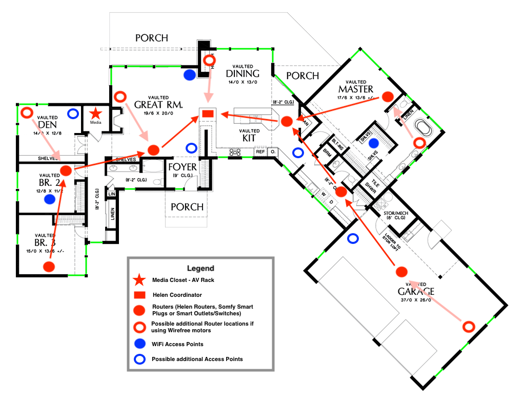
This layout shows a ~2500 sq ft home ideal for new construction or remodels where wiring can be run for a Zigbee mesh network including the Helen Coordinator, Low Voltage Zigbee Shades with built-in routers, and additional routers.
Shade Layout #
The green lines represent 47 Zigbee shades throughout the home. These may be a mix of Low Voltage and WireFree motors depending on installation requirements and wiring availability.
Routing Design #
Solid red circles indicate router nodes (Low Voltage shades or Zigbee plugs) forming a mesh with a maximum of 3 hops to the Helen Coordinator.
Red outlined circles show where additional routers would be needed if using WireFree motors while maintaining a reliable 3-hop path.
Wi-Fi Design #
Blue filled circles mark planned Wi-Fi access point locations. Blue outlined circles suggest optional expansion areas for wireless coverage.
Router (LV Shade/Plug)
Additional Router Location
Wi-Fi Access Point
Optional Wi-Fi Expansion
Shade Location
Retrofit Project Design #
Retrofit Best Practices
When running new wires is not feasible, WireFree Zigbee shades provide a wireless solution. Retrofit projects require extra planning to ensure reliable mesh coverage because battery-powered shades cannot act as routers.
Key Planning Steps #
Use a Wi-Fi analyzer to identify clear spectrum for Zigbee
Identify constant power sources for routers (existing outlets, switched circuits to avoid)
Place routers every 15-20 feet - closer in brick, concrete, or multi-floor homes
Plan for central coordinator placement when possible (consider extending RS-232)
Router Options for Retrofit #
Zigbee smart plugs: Plug into existing outlets; can control a lamp or simply remain plugged in
Dedicated Zigbee routers: Smaller footprint; some models are POE-powered
Low Voltage shades in key locations: If some windows have accessible power, use LV motors there to add routing
Quick Design Checks #
Coordinator can communicate with at least 2 routers
Every shade is within 2-3 hops from the coordinator
No Zigbee routers placed directly next to Wi-Fi access points
Routers are placed in open areas, not behind furniture or inside cabinets
Retrofit Challenge
When the Coordinator must be placed in a corner (e.g., in a media closet), shades on the far end of the building must make multiple hops. This can reduce reliability and slow response times. When possible, relocate the coordinator to a more central location.
Retrofit - Zigbee Mesh Example (Wireless Shades) #
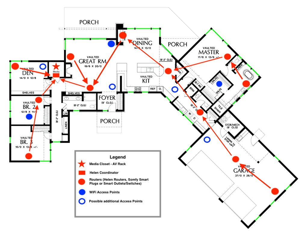
This floor plan illustrates a retrofit installation using WireFree Zigbee shades where running new wires is not feasible. The Helen Coordinator is placed in the Media Closet alongside the TRO.Y gateway.
Shade Layout #
The green lines indicate 47 Zigbee wireless shades. These rely entirely on wireless mesh routing for communication.
Routing Challenges #
This example shows how shades on the far end of the house must make multiple hops to reach the Coordinator. When the Coordinator is not centrally located, reliability may suffer.
Even if a router is physically close to a shade, if it is part of a path exceeding 3 hops to the Coordinator, communication issues can occur.
Router (Plug/Powered Device)
Additional Router Location
Wi-Fi Access Point
Potential Wi-Fi Addition
Shade Location
Lesson from This Example
A centrally placed Coordinator significantly reduces hop count and improves reliability. When possible, relocate the Coordinator to a central location even in retrofit situations. This may require extending the RS-232 connection (up to 50 feet maximum).
Router Placement Guidelines #
Router Spacing and Quantity
15-20 ft
Maximum Router Spacing
1 per 6-8
Routers per Shades
10-15 ft
Range Extension per Router
2-3 max
Hops to Coordinator
Placement Rules #
Spacing: Every 15-20 feet maximum; closer in challenging environments (brick, concrete, multi-floor)
Quantity: Approximately 1 router per 6-8 shades as a starting point
Location: Open areas preferred; not behind TVs, inside cabinets, or near metal objects
Separation: Maintain distance from Wi-Fi access points
Devices That Can Act as Routers #
Low Voltage Zigbee Motors: Built-in routing when constantly powered
Zigbee Smart Plugs: Easy to deploy in existing outlets
Dedicated Zigbee Routers: POE-powered options available
Field Tip
Every install is different based on building materials, layout, and interference. Always keep extra Zigbee routers and smart plugs on your truck. Being able to add a router on site is often the difference between completing the job and scheduling a callback.
Locations to Avoid #
Do Not Place Routers or Coordinator Near: #
Location/Item | Why to Avoid |
|---|---|
Wi-Fi access points | Direct interference source, especially if on overlapping channels |
Microwave ovens | Generate broadband 2.4 GHz interference during operation |
Wireless HDMI transmitters | Continuous high-power interference |
Inside metal AV racks | Acts as a Faraday cage, blocking signals |
Behind TVs | Metal chassis blocks signal propagation |
Inside closed cabinets | Limits signal propagation, especially if cabinet has metal components |
Near large metal objects | Reflects and blocks signals unpredictably |
In corners of the building | Maximizes hop count to devices on the opposite side |
Common Mistake
Placing the Helen Coordinator in an AV rack in the corner of the home. This forces all shades to make maximum hops and puts the coordinator near interference sources like wireless HDMI and networking equipment. Central placement is always better.
Verification and Documentation #
SILQ Signal Quality Reference
SILQ (Signal Quality) values in Helen Diagnostics indicate the health of the mesh network. Use these values to verify your design is working properly.
Device Type | Good SILQ Value | Notes |
|---|---|---|
End Devices (WireFree Shades) | 82+ | Battery-powered devices have lower transmit power |
Routers (LV Shades, Plugs) | 50+ | Higher transmit power allows lower threshold |
Low SILQ Values
If SILQ values are below thresholds, investigate: interference sources nearby, physical obstacles between devices, insufficient router coverage, or channel conflicts. Consider adding routers or changing the Zigbee channel.
#
Pre-Installation Checklist #
Complete these items before arriving on site:
Survey wireless environment (Wi-Fi channels, other Zigbee systems)
Document all 2.4 GHz devices on site
Plan central coordinator placement (verify max 50 ft RS-232 distance)
Calculate router quantity (1 per 6-8 shades minimum)
Identify constant power sources for routers
Select Zigbee channel (25 recommended; coordinate with other systems)
Verify no routers planned near Wi-Fi access points
Confirm wiring paths (new construction) or outlet locations (retrofit)
Coordinate with other trades if applicable
Load extra routers and smart plugs on truck
Post-Installation Verification #
Complete these verification steps before leaving the job site:
Verify all devices discovered and paired in Helen
Check SILQ values meet thresholds (82+ end devices, 50+ routers)
Test shade operation from all locations
Verify 2-3 hop maximum for all devices
Test mesh self-healing (temporarily power off one router, verify shades still respond)
Document final mesh topology for customer records
Provide customer with Zigbee channel and system information
Brief customer on what to tell future contractors about the system
Success Criteria
All shades respond within 1-2 seconds, SILQ values meet thresholds, and the mesh self-heals when a router is temporarily unavailable. Document these results before leaving the site.
Customer Handoff Information #
Provide the customer or building manager with the following information for future reference:
Zigbee channel in use (e.g., Channel 25)
Location of Helen Coordinator
Number and general locations of Zigbee routers
Contact information for support
Advise the customer:
Do not unplug Zigbee routers (smart plugs providing routing)
Inform future contractors (IT, AV) about the Zigbee system and channel
Contact support before making changes to Wi-Fi or adding new Zigbee systems