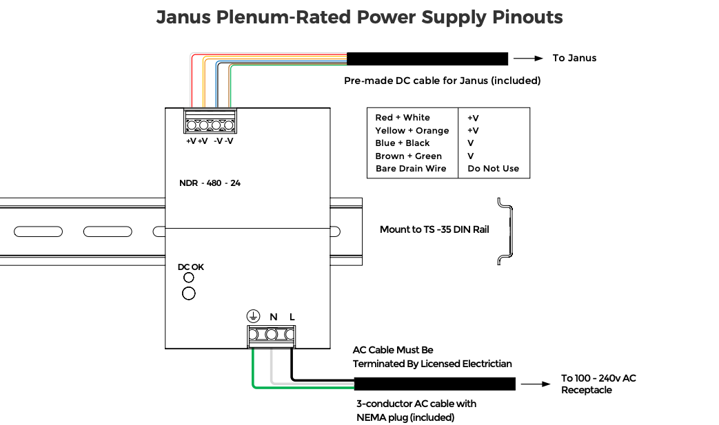
24v DC – 485: Using 5 Conductor Wire #
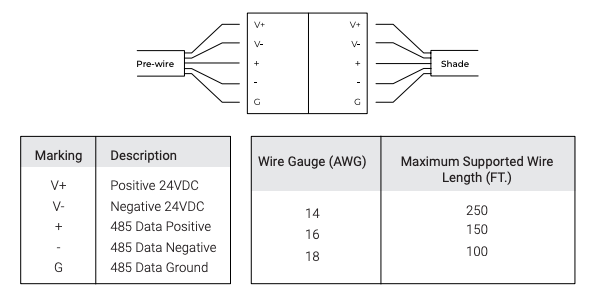
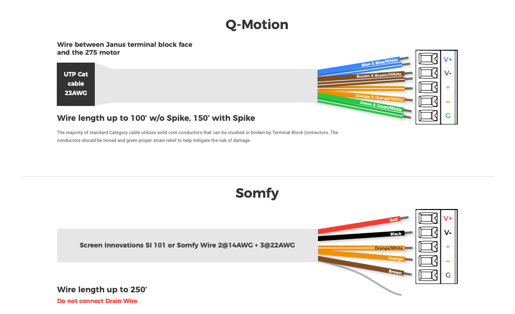
24v DC – 485 : Using 5 CAT5/6 #
Wire between Janus terminal block face and the motor only.
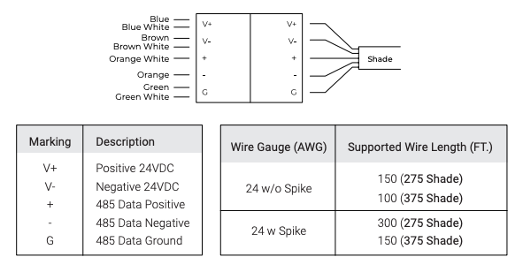
On the Phoenix Connector: #
V+ = BLUE PAIR
V- = BROWN PAIR
+ = ORANGE WHITE
– = ORANGE
G = GREEN PAIR
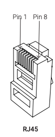
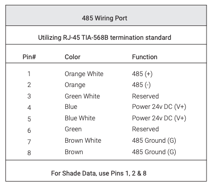
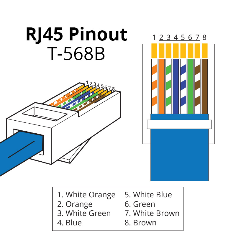
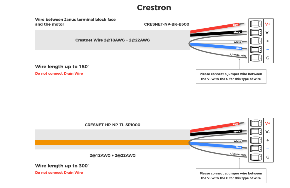
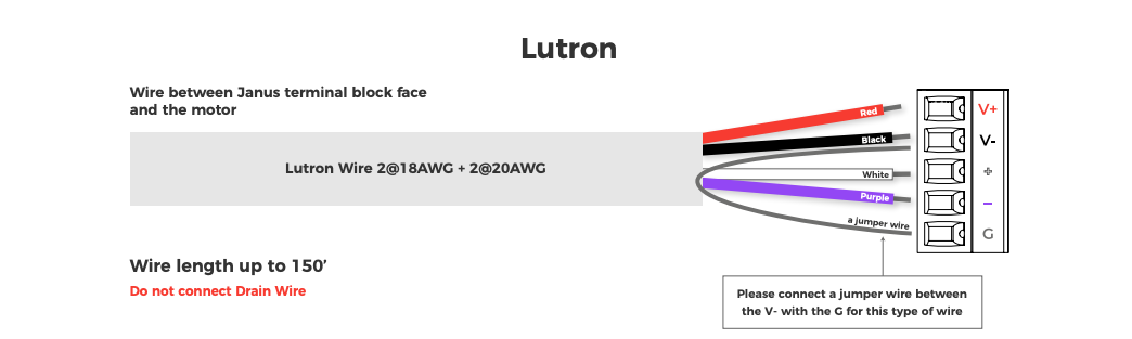
24v DC – 485: Using 4 – Conductor Wire #
If the pre-wire does not have a third insulated data conductor for the 485 ground, terminate the wire as shown below.
Use the same termination on both ends.
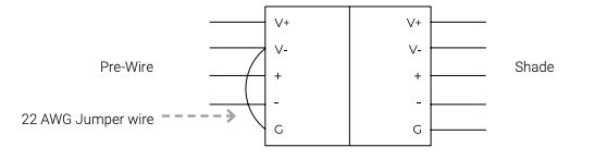
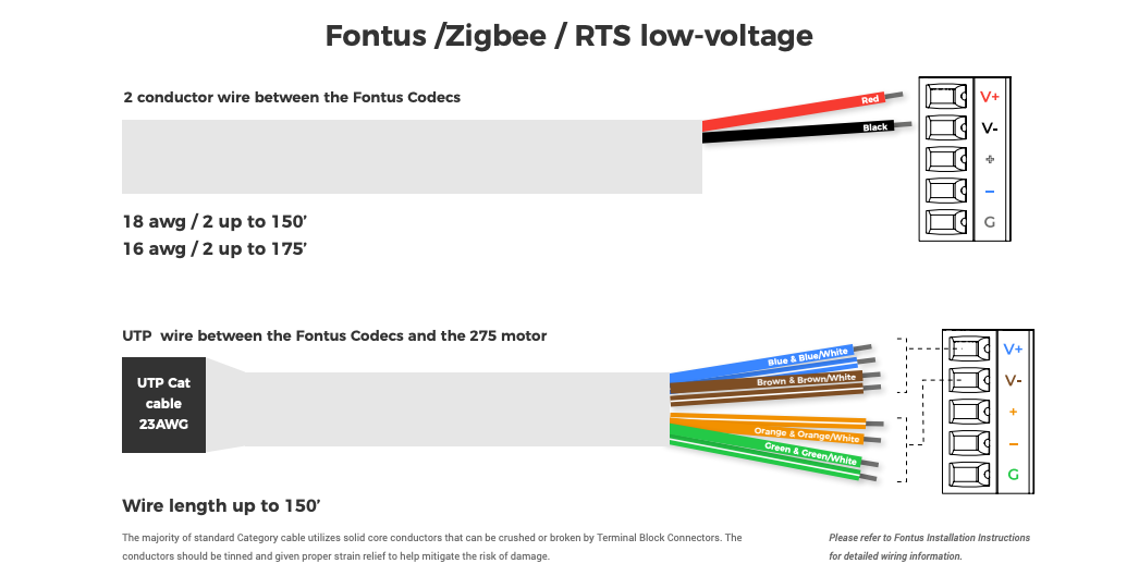
WIRING – 24v DC – RTS #
For guaranteed motor performance the supplied voltage for 24v motors must be 24v DC.
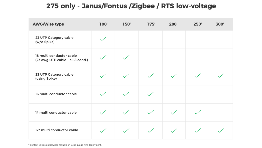
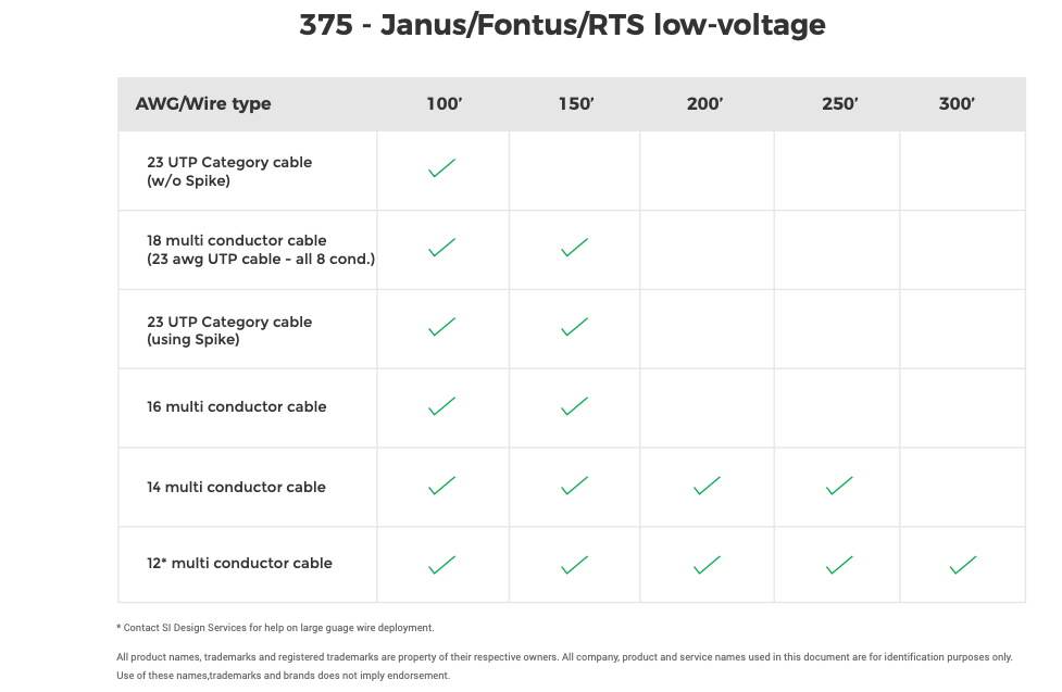
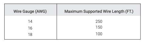
See the table below for maximum wire lengths.
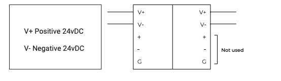
If the motors are powered using a Power Distribution Enclosure connect the motors to the “+24v DC” and “-24v DC” ports on the terminal blocks.
The RS485 ports are unused.
Wire Topologies #