Screen Overview #
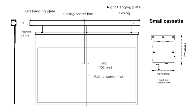
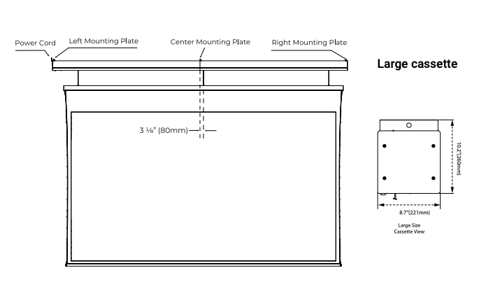
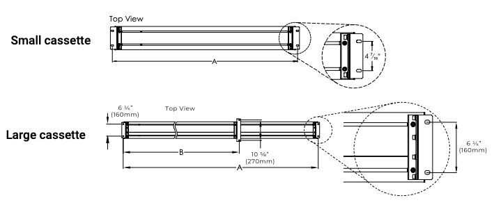
Important: Due to structural reasons, the screen position is offset from the center of the casing:
4¼” (105mm) for small cassette screens
3⅛” (80mm) for large cassette screens, to the right
Account for this offset when determining mounting hole locations and maintain 0.4 meters clearance on the power cord side for future service
Suspended Ceiling Installation Method #
Step 1: Measure and Mark #
Measure the distance for the four hanging screw holes on the screen (refer to diagram below)
Calculate the screen’s installation position and mark the four hole locations for threaded rods
Cut threaded rods to required length and secure them in place
Step 2: Lift and Adjust #
Use lifting equipment to raise the screen to installation position
Adjust the installation bracket horizontally to ensure threaded rods align with and pass through bracket holes
Step 3: Fasten and Level #
Fasten the nuts onto the threaded rods
Adjust nut height and use a level to ensure screen is perfectly horizontal
Double-check all connections are secure
Precautions:
Screen fabric is offset to the right from casing – account for this when calculating installation position
For closed suspended ceiling installations, reserve about 15¾” (400mm) of space on the power supply side for maintenance
Pay attention to screen material’s projection surface orientation to avoid installing backward


Setting Limits #
Upper Limit Setting #
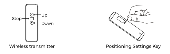
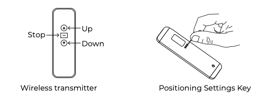
Briefly tap the programming button on the back of remote control until LED light in programming hole illuminates
Move screen to desired upper limit position
Press “Stop” button
Briefly press program button and verify LED light has turned off
Lower Limit Setting (Drop Height) #
Briefly tap the programming button on the back of remote control until LED light illuminates
Move screen to desired lower limit position
Press “Stop” button
Briefly press program button and verify LED light has turned off
Warning: To guarantee the screen’s precise positioning and safety, DO NOT use the motor adjustment key to adjust limits.
Critical Safety Information:
Exercise extreme caution when setting screen’s retraction height
Over-adjusting may cause bottom bar to become lodged in casing, potentially damaging screen or causing bottom bar to drop
Careful consideration needed when setting deployment height
Steel cable should not extend beyond 5 meters – exceeding this limit could reverse cable reel, hindering screen retraction
Changing Motor Direction #
Push and hold the Programming Button until the screen jogs once
Controlling the Screen #
Warning: An activation button has been added to safeguard the internal steel cable system. Before turning on power, ensure you completely remove the yellow adhesive tape from the screen. Failing to do so could damage internal steel cables and create safety risks.
Zero G Pro has 5 control methods:
Manual control (cycle button)
Wireless control
Dry contact control
RS485 or RS232 control
12-Volt Trigger
Manual Control #
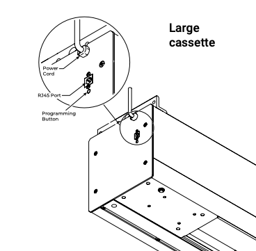
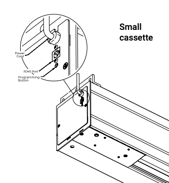
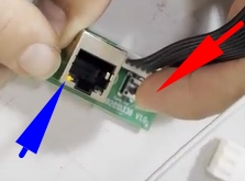
Manual control button is located on left side of enclosure near RJ45 connection
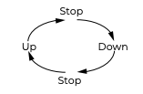
Pressing button commands: extend → stop → retract → stop in sequence
RF Remote Control #
Down button: Screen extends to set position
Stop button: Screen pauses
Up button: Screen retracts
Pairing/Unpairing (Remote pre-paired at factory) #
Method 1:
Press and hold cycle button for 3 seconds – screen will jog once, entering pairing mode
Within 10 seconds, press both up and stop buttons on remote simultaneously
Screen will jog again, indicating pairing is complete
Odd-numbered operations pair, even-numbered operations delete code
Method 2:
Disconnect screen’s power for 10 seconds, then reconnect
Within 10 seconds, press both up and stop buttons on remote simultaneously
Screen will jog slightly, indicating pairing is complete
Individual Pairing for One-to-One Control #
To ensure precise one-to-one control, each device must be paired individually:
When pairing with single screen, ensure all other screens are completely powered off
Power on and pair each screen one at a time
This guarantees each control is uniquely mapped to specific screen
Important: Before re-pairing, existing pairing memory on each screen must be cleared.
Memory Reset Procedure #
Press and hold button on screen for 5 seconds
When indicator LED begins flashing rapidly, press button again
Memory will be cleared and device ready for re-pairing
Dry Contact, RS485/RS232 Control, 12V Trigger #
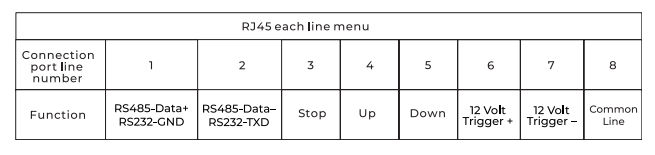
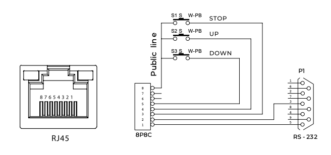
RS485/RS232 Port Settings #
Data Bits: 8 bits
Stop Bit: 1 bit
Baud Rate: 2400
Hex Control Codes #
Up: FFEEEEEEDD
Stop: FFEEEEEECC
Down: FFEEEEEEEE
Address code: FFEEEEEEAA (for some central controls)
Learn address code: FFXXXXXXAA (XXXXXX = hex characters other than E and 5)
Important RS232/RS485 Notes:
If unable to control screen, try switching the two control wires
Wiring loop resistance should be less than 20Ω
Do not run wires parallel to strong interference sources
For RS232: send data string twice in succession with 2400, n, 8, 1 settings
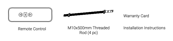
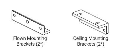
Parts in the Box #
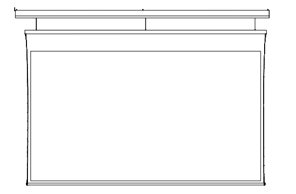
Note: This image shows Pure White material with visible black border. Black printed border will not be visible with Carbon Black material.
If flown installation, you need to provide your own turnbuckles
For larger cassette sizes, 3 brackets will be provided