
Overview #
This guide provides technical procedures for diagnosing and resolving Zigbee connectivity issues in Screen Innovations shade control systems. It covers the TRO.Y 2 gateway, Helen coordinator/router architecture, and the RF considerations necessary for reliable wireless shade operation.
TRO.Y 2 communicates with Helen via RS-232 (Do not exceed 50′ from the Troy’s Helen port to the Helen Coordinator). Helen manages the Zigbee mesh network.
What This Guide Covers #
Section | Content | Use When |
|---|---|---|
Protocol basics, device roles, mesh topology | Training, general understanding | |
2.4 GHz spectrum, interference sources, channel planning | Site planning, interference diagnosis | |
Residential, luxury, commercial considerations | Pre-installation planning | |
Step-by-step troubleshooting workflow | Active troubleshooting | |
Specific problems and solutions | Known issue lookup | |
Wi-Spy/Chanalyzer procedures | Advanced diagnosis, documentation |
Zigbee Fundamentals #
Zigbee Protocol Overview
Zigbee is an IEEE 802.15.4-based wireless protocol designed for low-power, low-data-rate mesh networking. Unlike Wi-Fi (point-to-access-point) or Bluetooth (point-to-point), Zigbee creates a self-healing mesh where messages can route through multiple paths to reach their destination.
2.4 GHz
Operating Frequency (ISM Band)
250 kbps
Maximum Data Rate
+20 dBm
Maximum Transmit Power
16
Available Channels (11-26)
Zigbee Device Roles #
Role | Function | SI Implementation | Power Source |
|---|---|---|---|
Coordinator | Creates network, assigns addresses, maintains routing tables | Helen Coordinator | RS-232 from TRO.Y 2 |
Router | Relays messages, extends network range, maintains child devices | Zigbee Router, Powered LV Shades | POE or Low Voltage |
End Device | Sends/receives messages only, does NOT relay | Wirefree (Battery) Shades | Battery |
WARNING: ⚠️
Critical Design Consideration: Battery-powered Wirefree Zigbee shades function as End Devices only. They do NOT relay messages for other devices. Network designs must account for this by ensuring adequate router coverage for all Wirefree shade locations.
Mesh Topology Concepts #
Zigbee Mesh Network Topology
 Routers create redundant paths. If one path fails, messages route through alternatives. End devices connect to their nearest router.
Screen Innovations System Components
TRO.Y 2 Gateway #
TRO.Y 2 is the central controller for SI shade systems. It does not transmit Zigbee directly; instead, it communicates with Helen via RS-232 serial connection.
Connection to Helen: RS-232 serial (dedicated Helen port)
Maximum cable length: 50 feet
Do NOT use POE injector for Helen Coordinator connection
Helen Coordinator #
The Helen Coordinator creates and manages the Zigbee network. There is exactly one Coordinator per TRO.Y 2 system.
Placement: Central, open location with line-of-sight to shades
Avoid: Behind TVs, in AV racks, metal enclosures, near microwaves
Power: From TRO.Y 2 Helen port (NOT POE)
Antenna: Verify not damaged, kinked, or broken
Zigbee Router #
Additional Helen units configured as Routers extend the mesh network range.
Power: POE injector (no network cable required into injector)
Placement: Strategic locations to fill coverage gaps
Spacing: Maximum 15-20 feet from nearest router or Coordinator
Shade Device Types #
Shade Type | Power | Zigbee Role | Mesh Impact |
|---|---|---|---|
Low Voltage (LV) Zigbee | 24V DC | Router + End Device | Extends network; relays for other devices |
Wirefree Zigbee | Battery | End Device Only | Does NOT relay; depends on nearby routers |
SUCCESS: ✅
Design Advantage: Each powered LV shade acts as a router. Installations with many powered shades naturally have robust mesh networks with multiple redundant paths.
Understanding SILQ Values #
SILQ (Signal Quality) is the primary metric for assessing Zigbee link health in Helen Diagnostics. It represents a composite score of signal strength and link quality.
SILQ Reference Values #
SILQ Range | Status | Interpretation |
|---|---|---|
82+ | Optimal | Strong signal, reliable communication |
50-81 | Acceptable for Routers | Adequate for router devices; marginal for end devices |
<50 | Poor | Unreliable; expect dropouts and delayed commands |
Interpreting SILQ Patterns #
Consistently low SILQ: Physical distance or obstruction issue. Add routers or reposition Helen.
Fluctuating SILQ: RF interference (Wi-Fi, microwave, etc.). Change Zigbee channel or identify interference source.
SILQ drops at specific times: Periodic interference source. Correlate with household activities.
The RF Environment #
Understanding the 2.4 GHz RF environment is essential for successful Zigbee deployments. This section covers the technical realities of spectrum sharing and the industry-wide challenges that affect all wireless smart home systems.
The 2.4 GHz Spectrum Challenge #
The 2.4 GHz ISM (Industrial, Scientific, Medical) band is shared by multiple wireless technologies. This congestion is an industry-wide challenge, not specific to any single product or manufacturer.
“Wireless coexistence studies and mitigation technologies for unlicensed 2.4 GHz frequency bands have been around for at least 20 years. The issue is that different 2.4 GHz wireless technologies meet different needs for the same devices, and therefore must operate simultaneously without noticeable performance degradation.”— Embedded Computing Design (Silicon Labs)
Technologies Sharing 2.4 GHz #
Technology | Transmit Power | Channel Width | Typical Use |
|---|---|---|---|
Wi-Fi (802.11b/g/n) | up to +30 dBm | 20-40 MHz | Internet access, streaming |
Zigbee (802.15.4) | up to +20 dBm | 2 MHz | Smart home devices, shades |
Bluetooth | up to +20 dBm | 1 MHz (FHSS) | Audio, wearables, peripherals |
Thread/Matter | up to +20 dBm | 2 MHz | Smart home (newer devices) |
“Interference degrades wireless performance through message failures, resulting in more message retries. These issues can lead to reduced device responsiveness and increased power consumption.”— Silicon Labs Wi-Fi Coexistence Guide
The Power Imbalance #
Wi-Fi transmits at up to +30 dBm while Zigbee is limited to +20 dBm–a 10 dB difference representing 10x the power. When Wi-Fi and Zigbee signals collide, Zigbee loses.
“ZigBee and Wi-Fi channels both exist in the 2.4 GHz band, existing in the exact same frequency space. When deploying both Wi-Fi and ZigBee in the same environments, careful planning must be performed to make sure that they don’t interfere with each other. Operating a ZigBee network and a Wi-Fi network on the same frequency will cause them to interfere with each other. Usually, the ZigBee network will take the hit.”— MetaGeek Support
Wi-Fi and Zigbee Channel Overlap #
Wi-Fi channels 1, 6, and 11 (the non-overlapping channels) directly overlap with Zigbee channels 11-24. Only Zigbee channel 25 sits above typical Wi-Fi traffic.
Channel Frequency Reference Charts #
Wi-Fi and Zigbee Channel Overlap

Zigbee channel 25 sits above Wi-Fi channel 11, providing the best separation. TRO.Y/Helen supports channels 11-25.
Wi-Fi Channels 1, 6, 11

The three non-overlapping Wi-Fi channels in the 2.4 GHz band.
Channel Conflict Reference #
Wi-Fi Channel | Frequency Range | Affected Zigbee Channels | Recommended Action |
|---|---|---|---|
Channel 1 | 2401-2423 MHz | 11, 12, 13, 14 | Use Zigbee 25 or 15+ |
Channel 6 | 2426-2448 MHz | 15, 16, 17, 18, 19, 20 | Use Zigbee 25 or 11-14 |
Channel 11 | 2451-2473 MHz | 21, 22, 23, 24 | Use Zigbee 25 or 15 |
WARNING: ⚠️
Sideband Interference: Wi-Fi signals include sideband lobes extending beyond the main channel. These can affect Zigbee channels that appear to be outside the Wi-Fi channel. Spectrum analysis with Wi-Spy reveals the true extent of interference.
“ZigBee channels 25-26 aren’t immune either, because they can be caught in Wi-Fi channel 11’s sideband lobe. ZigBee channel 26 is usually relatively unaffected by Wi-Fi, but many ZigBee devices do not support it.”— MetaGeek
Non-Wi-Fi Interference Sources #
Wi-Fi is not the only source of 2.4 GHz interference. Many common household and commercial devices operate in this band.
Source | Impact | Characteristics | Mitigation |
|---|---|---|---|
Microwave ovens | SEVERE | Wideband, high-power bursts during operation | Position Helen 6+ ft away; add routers on opposite side of kitchen |
2.4 GHz baby monitors | HIGH | Continuous transmission when active | Recommend DECT 6.0 monitors (1.9 GHz) |
Wireless HDMI/video | HIGH | High-power, continuous signal | Identify in AV rack; consider wired alternatives |
Bluetooth audio | MODERATE | Frequency-hopping; impact during streaming | Generally tolerable; note heavy-use areas |
USB 3.0 devices | MODERATE | RF noise leakage from cables/ports | Keep Helen away from computers; use shielded cables |
Other Zigbee Systems Common Zigbee devices that may share the 2.4 GHz spectrum:
| MODERATE | Channel collision if same channel used; multiple coordinators can cause network congestion | Coordinate channels between systems; ensure each system uses different Zigbee channel (e.g., Hue on 11, Helen on 25) |
Gaming peripherals | MODERATE | Logitech Unifying, Razer Hyperspeed | Note gaming areas; usually tolerable |
“Any device using the open 2.4 GHz spectrum could interfere with Zigbee such as Bluetooth or gaming devices like Logitech ‘Unifying’ or ‘Lightspeed’ or Razer ‘Hyperspeed Wireless’. This includes devices that you may not realize are 2.4 GHz.”— Home Assistant Community
Physical Obstructions and Signal Attenuation #
Building materials affect Zigbee signal propagation. Understanding attenuation helps plan router placement.
Material | Typical Attenuation | Impact | Design Consideration |
|---|---|---|---|
Standard drywall | 2-3 dB | Low | Multiple walls acceptable with adequate power |
Wood framing | 3-5 dB | Low | Standard construction; minimal concern |
Brick/Stone | 6-10 dB | Moderate | Add routers to reduce hop distance |
Concrete (no rebar) | 10-15 dB | Moderate-High | Router on each side of concrete walls |
Concrete with rebar | 15-25 dB | High | Router on each floor; do not rely on floor penetration |
Low-E glass / Mirrors | 15-30 dB | High | Router on each side of glass walls |
Metal (mesh, foil insulation) | 20-40+ dB | Severe | Near-total block; must route around |
DANGER: ⚠️
Foil-backed insulation acts as a near-complete RF barrier. In homes with this insulation type, plan for routers on each side of insulated barriers. This is common in newer energy-efficient construction.
Deployment Scenarios #
Different environments present different RF challenges. Use these guidelines for pre-installation planning and site assessment.
#
Standard Residential #
Single-family homes under 4,000 sq ft
Most common deployment scenario. Consumer mesh Wi-Fi systems (eero, Google, Orbi) create unpredictable channel conditions.
Common Challenges
Consumer Wi-Fi with automatic channel selection
Dense Bluetooth environments (audio, wearables)
Microwave ovens, baby monitors
Neighbor Wi-Fi in dense neighborhoods
Planning Guidelines
Default Zigbee to Channel 25
Central Helen placement in open area
Powered shades typically provide sufficient routing
Zigbee Routers: 1 per 6-8 shades, or to extend range (10′-15′)
Every install is different–keep extra Zigbee routers/smart plugs on your truck
Luxury Residential #
Estates 5,000-15,000+ sq ft, multi-story
Complex deployments requiring careful mesh planning. Often include enterprise networking and multiple smart home systems.
Common Challenges
Large distances between devices
Multi-floor with concrete/rebar separation
AV racks with wireless HDMI transmitters
Multiple Zigbee ecosystems (Hue, SmartThings)
High-end finishes (mirrors, Low-E glass)
Planning Guidelines
Pre-installation Wi-Spy survey recommended
Coordinate Zigbee channel with existing systems
Zigbee Router on each floor (minimum)
Zigbee Routers: 1 per 6-8 shades, or to extend range (10′-15′)
Router spacing: 15-20 ft maximum
Request enterprise Wi-Fi with manual 2.4 GHz control
Every install is different–keep extra Zigbee routers/smart plugs on your truck
Commercial / MDU #
Offices, hotels, multi-dwelling units
Highest RF complexity. Dense competing networks, enterprise Wi-Fi, and IT coordination requirements.
Common Challenges
Dense enterprise Wi-Fi deployments
Multiple tenants with independent networks
IT policies restricting RF modifications
Metal furniture and partitions
Conference room AV systems
Planning Guidelines
Wi-Spy survey recommended for documentation
Coordinate with IT on 2.4 GHz channel allocation
May require dedicated Wi-Fi channels (1 & 6 only)
Zigbee Routers: 1 per 6-8 shades, or to extend range (10′-15′)
Consider multiple TRO.Y/Helen systems for zones
Document baseline performance metrics
Every install is different–keep extra Zigbee routers/smart plugs on your truck
Managed vs. Unmanaged Wi-Fi Systems #
The ability to manually control Wi-Fi channel selection is critical for Zigbee coexistence in professional installations.
Consumer Mesh Systems (Unmanaged) #
Systems like eero, Google Wifi, and Netgear Orbi automatically select and change 2.4 GHz channels without user control. This creates unpredictable RF conditions where the Wi-Fi network may shift onto the same frequencies as Zigbee at any time.
WARNING: ⚠️
When Zigbee issues occur with unmanaged mesh Wi-Fi: Document the RF environment with Wi-Spy. If interference is confirmed, recommend migration to managed Wi-Fi with manual 2.4 GHz channel selection. This is the only long-term solution for reliable Zigbee coexistence.
Enterprise/Managed Wi-Fi Systems #
System | Manual 2.4 GHz Control | Notes |
|---|---|---|
Ubiquiti UniFi | Yes | Full channel control; good value for residential |
Cisco Meraki | Yes | Cloud-managed; detailed RF analytics |
Ruckus | Yes | Enterprise-grade; advanced RF optimization |
Aruba | Yes | AI-powered channel optimization |
eero | No | Automatic only; cannot coordinate with Zigbee |
Google Wifi | No | Automatic only |
“If you don’t need 2.4 GHz (and let’s be honest, it’s mostly for IoT and legacy devices), you can switch a radio to dual 5 GHz mode instead.”— Cisco Meraki RF Best Practices
Diagnostic Procedures #
This section provides systematic procedures for diagnosing Zigbee connectivity issues. Work through these procedures in order for efficient troubleshooting.
Diagnostic Workflow
1. Helen Diagnostics
2. Physical Assessment
3. Channel Optimization
4. Mesh Rebuild
5. Spectrum Analysis
Procedure 1: Helen Diagnostics Analysis #
Accessing Helen Diagnostics #
Navigation: TRO.Y Dashboard scroll to bottom Helen Diagnostics Start Helen Diagnostics
Data Collection #
Record the following for each device showing issues:
Parameter | Location in Diagnostics | What to Record |
|---|---|---|
SILQ Value | Device list | Current value (0-100 scale) |
Device Type | Device list | Router or End Device |
Parent/Route | Routing table | Which router the device connects through |
Zigbee Channel | Network info | Current channel (11-25) |
SILQ Analysis #
SILQ Pattern | Probable Cause | Next Step |
|---|---|---|
Consistently low (<50) | Physical distance or obstruction | Procedure 2: Physical Assessment |
Fluctuating (varies by 20+ points) | RF interference | Procedure 3: Channel Optimization |
Drops at specific times | Periodic interference source | Correlate with activities; consider Procedure 5 |
Good SILQ but commands fail | Routing issue or mesh problem | Procedure 4: Mesh Rebuild |
Generating Zigbee Route Graph #
Navigation: Integration Settings Wireless Bridge Settings Generate Zigbee Route Graph
The route graph visualizes the mesh topology. Look for:
Long chains: Devices routing through many hops increase latency and failure probability
Single points of failure: Many devices routing through one router
Unexpected routing: Device routing through distant router instead of nearby one
Procedure 2: Physical Deployment Assessment #
Helen Coordinator Inspection #
Verify the following physical conditions:
Requirement | Verification Method | If Not Met |
|---|---|---|
Open-air mounting | Visual inspection | Relocate from enclosures, behind TVs, AV racks |
Central to shade layout | Compare Helen location to shade floorplan | Consider relocation or add routers |
Antenna undamaged | Physical inspection for kinks, breaks | Replace Helen if antenna damaged |
Connected to TRO.Y Helen port | Verify cable connection | Do NOT use POE injector for Coordinator |
6+ ft from interference sources | Check proximity to microwaves, wireless HDMI | Relocate Helen or interference source |
Router Network Assessment #
For each floor and zone:
Map all router locations (Zigbee Routers, powered shades)
Measure distances between routers (should not exceed 20 ft)
Identify gaps where no router coverage exists
Note physical obstructions between routers (concrete, metal, glass)
Router Spacing Guidelines #
Construction Type | Maximum Router Spacing | Notes |
|---|---|---|
Standard wood/drywall | 15-20 ft | Through 2-3 walls acceptable |
Brick/stone walls | 10-15 ft | Add intermediate routers |
Concrete floors | N/A (floor penetration unreliable) | Router required on each floor |
Metal/foil barriers | N/A (signal blocked) | Router on each side of barrier |
WARNING: ⚠️
Physical proximity does not guarantee routing. A shade 3 ft from a router may route through a different router 30 ft away if that path was established first. Always verify actual routing using the Zigbee Route Graph.
Procedure 3: Zigbee Channel Optimization #
Indications for Channel Change #
SILQ values fluctuate without physical changes
Commands delayed or fail intermittently
Issues correlate with Wi-Fi activity
Current channel overlaps known Wi-Fi channels
Channel Change Procedure #
Document current state: Record current Zigbee channel and SILQ values for key devices
Navigate: Integration Settings Wireless Bridge Settings Change Zigbee Channel
Select new channel:
Channel 25 (recommended): Maximum separation from Wi-Fi
Channel 15 (alternative): Between Wi-Fi channels 1 and 6
Apply changes: System will prompt to reboot Helen
Wait for mesh reformation: Allow 5-10 minutes for all devices to rejoin
Verify: Re-run Helen Diagnostics; compare SILQ values to baseline
SUCCESS: ✅
TRO.Y/Helen supports Zigbee channels 11-25. Channel 26 is not supported. Channel 25 is the recommended default for new installations.
If Other Zigbee Systems Are Present #
When the site has multiple Zigbee coordinators (Philips Hue, SmartThings, Amazon Echo, etc.):
Identify all Zigbee systems and their current channels
Ensure each system uses a different channel (minimum 2-channel separation)
Document the channel allocation for future reference
Procedure 4: Mesh Network Rebuild #
When to Rebuild the Mesh #
After adding or relocating routers
After changing Zigbee channel
When routing paths appear suboptimal
After resolving interference issues
When devices route through distant routers despite closer options
Rebuild Procedure #
1: Power cycle TRO.Y 2
Unplug power, wait 10 seconds, reconnect. Wait for full boot (approximately 2 minutes).
2: Power cycle Helen Coordinator
Disconnect RS-232 from TRO.Y, wait 10 seconds, reconnect. Coordinator will reinitialize network.
3: Power cycle all routers sequentially
For each Zigbee Router and powered shade: power off, wait 30 seconds, power on. This forces route rediscovery.
4: Do NOT touch battery-powered devices
Wirefree shades will automatically rejoin when they detect routing updates. Forcing a reset is unnecessary.
5: Allow mesh stabilization
Wait 10-15 minutes for all routing tables to update and stabilize.
6: Verify new routing
Generate new Zigbee Route Graph. Compare to previous routing and verify improvements.
Procedure 5: Escalation to Spectrum Analysis #
Indications for Spectrum Analysis #
Proceed to Wi-Spy spectrum analysis when:
Procedures 1-4 do not resolve the issue
SILQ values fluctuate with no identified cause
Issues occur at specific times suggesting periodic interference
Customer disputes that interference is the cause
Commercial installation requires documentation
Pre-installation survey for complex environments
Spectrum analysis provides objective RF environment data. It documents interference sources that Helen Diagnostics cannot detect, including Wi-Fi from neighbors, non-Wi-Fi devices, and intermittent sources. This data is essential for demonstrating environmental factors to customers and for coordinating with IT departments.
Issue Resolution #
Reference this section for specific issue resolution procedures. Each issue includes symptoms, likely causes, and step-by-step resolution.
Issue: Device Not Discovered During Pairing (Shades & Routers) #
Symptoms #
Shade or Zigbee Router does not appear in device table during pairing window
Pairing window times out with no device found
Device previously paired but now won’t re-discover after reset
Some devices pair successfully while others fail in the same area
Likely Causes #
Device Type | Common Causes |
|---|---|
LV Zigbee Shade |
|
Wirefree Shade |
|
Zigbee Router |
|
Resolution Procedure: Shades #
Step | Action | Expected Result |
|---|---|---|
1 | Verify power: | Motor responds to manual button press (jogs or LED) |
2 | Factory reset motor (if previously paired elsewhere): | Motor resets to factory defaults |
3 | Open pairing window: | Pairing window opens (120 seconds) |
4 | Put shade in pairing mode: | LED indicates pairing mode |
5 | Nano only — check for Bluetooth mode: If the Nano motor did not enter discovery mode after the 2-jog hold, rapidly press the motorhead button 10 times in quick succession. If the motor was in Bluetooth mode, it will jog to confirm the switch back to Zigbee mode and the LED will begin slow blinking amber (discovery mode active). | Motor jogs to confirm mode switch; amber LED blinks slowly |
6 | If not discovered: Temporarily move Helen Coordinator within 10 ft of shade | Shade appears in device table |
7 | If still not discovered: Add Zigbee Router between Coordinator and shade location | Improved RF coverage for pairing |
8 | Verify motor function via Somfy TaHoma Pro App (Bluetooth): | Motor confirmed functional; firmware current; ready for Eco-System discovery |
Resolution Procedure: Zigbee Routers #
Step | Action | Expected Result |
|---|---|---|
1 | Verify POE power: Confirm POE injector is powered and connected to Zigbee Router | Router LED indicates power |
2 | Position for pairing: Move router within 15 ft of Helen Coordinator for initial pairing | Router within reliable range |
3 | Factory reset router (if previously paired): | Router ready for new network |
4 | Open pairing window on TRO.Y and put router in pairing mode | Router appears in device table |
5 | After pairing: Move router to final location; allow 5 minutes for mesh stabilization | Router shows in network topology |
WARNING: ⚠️
Common Mistakes:
Opening pairing window AFTER putting device in pairing mode (order matters)
Not waiting for LED confirmation of pairing mode
Attempting to pair device that’s already on another Zigbee network
Wirefree shades in sleep mode–always wake with button press first
POE injector not plugged in (no network cable required, just power)
SUCCESS: ✅
Pro Tip: If multiple devices fail to pair in the same area, this strongly suggests RF interference or insufficient mesh coverage. Run Helen Diagnostics on nearby paired devices–if SILQ is below 50, the area needs a router before attempting to pair additional devices.
Issue: Low SILQ / Weak Signal #
Symptoms #
SILQ value consistently below 82 for end devices
SILQ value consistently below 50 for routers
Intermittent disconnections or slow command response
Likely Causes #
Physical distance exceeds reliable range
Physical obstruction (concrete, metal, glass) in signal path
Helen or router poorly positioned
Damaged antenna
Resolution Procedure #
Identify affected devices: Run Helen Diagnostics; sort by SILQ value
Map physical locations: Plot low-SILQ devices on floorplan
Identify obstructions: Check for concrete, metal, glass between Helen and affected devices
Reposition Helen: Move to more central, open location if possible
Add routers: Position Zigbee Router or ensure powered shade exists between Coordinator and affected devices
Inspect antenna: Check Helen antenna for physical damage, kinks, or breaks
Rebuild mesh: After changes, execute Procedure 4 (Mesh Rebuild)
Verify improvement: Re-run Helen Diagnostics; confirm SILQ improvement
SUCCESS: ✅
SILQ Targets: End devices (shades) should maintain SILQ of 82+. Routers can operate reliably at 50+. Values below these thresholds indicate the need for additional routing infrastructure.
Issue: Devices Dropping Off Network #
Symptoms #
Previously working shade stops responding
Device disappears from device table
Shade works intermittently then fails
Likely Causes #
Power loss to device
RF interference causing repeated communication failures
Router that device depended on was removed or lost power
Environmental change (new obstruction, moved furniture)
Resolution Procedure #
Verify power: Confirm device has not lost power (check breaker, transformer, wiring)
Check routing history: Review Zigbee Route Graph for the device’s previous path
Assess environmental changes: Has furniture been moved? New appliances installed? Construction?
Check for new interference: Any new 2.4 GHz devices in the area?
Delete and re-pair: Remove device from device table; re-discover
Add router if needed: If device repeatedly drops, add router to strengthen local coverage
If recurring: Perform Wi-Spy analysis to identify interference source
Issue: Commands Delayed or Out of Order #
Symptoms #
Shade responds several seconds after command
Multiple commands execute in wrong order
Commands appear to “queue up” then execute rapidly
Likely Causes #
RF interference causing message retries
Mesh routing through congested path
Too many commands sent too rapidly
TRO.Y firmware issue
Resolution Procedure #
Check TRO.Y firmware: Update to latest version if available
Review SILQ values: Run Helen Diagnostics; check for low values
Analyze routing: Check Zigbee Route Graph for long chains or bottlenecks
Test command spacing: Send commands with 1-2 second delays between
Change Zigbee channel: Move to channel 25 to reduce Wi-Fi interference
Note timing patterns: If delays occur at specific times, suspect periodic interference
If timing-related: Correlate with household activities (microwave, backups, streaming)
“Interference degrades wireless performance through message failures, resulting in more message retries. These issues can lead to reduced device responsiveness and increased power consumption.”— Silicon Labs
Issue: Fluctuating SILQ Values #
Symptoms #
SILQ values change significantly between diagnostic runs
Device works well sometimes, poorly other times
No physical changes to explain variation
Likely Causes #
RF interference from Wi-Fi or other 2.4 GHz sources
Periodic interference (microwave, baby monitor, wireless HDMI)
Neighbor Wi-Fi changing channels (common with eero, Google Wifi)
Resolution Procedure #
Document pattern: Run Helen Diagnostics multiple times over several hours; record SILQ values with timestamps
Correlate with activities: Note what activities are occurring during low-SILQ periods
Change Zigbee channel: Move to channel 25
If issues persist: Perform Wi-Spy spectrum analysis to identify interference source
Document findings: Spectrum captures provide evidence of environmental factors
WARNING: ⚠️
Fluctuating SILQ is a strong indicator of RF interference. Physical issues (distance, obstructions) cause consistently low values. Fluctuating values point to interference that varies over time. Wi-Spy analysis is recommended to identify the source.
Spectrum Analysis with Wi-Spy #
Spectrum analysis provides objective data about the RF environment that Helen Diagnostics cannot reveal. This section covers equipment, procedures, and interpretation for professional RF troubleshooting.
Why Spectrum Analysis #
Helen Diagnostics shows signal quality between devices–but not what’s causing degradation. Wi-Spy + Chanalyzer visualizes the complete 2.4 GHz spectrum: Wi-Fi networks, non-Wi-Fi interference, and hidden sources affecting Zigbee performance.
Document RF EnvironmentCapture objective evidence of interference sources
Identify Hidden SourcesDetect microwaves, wireless video, neighbor networks
Validate Channel SelectionConfirm Zigbee channel is clear before/after changes
Generate ReportsProfessional documentation for customers and IT teams
Equipment Requirements #
Required Hardware #
Item | Description | Source |
|---|---|---|
Wi-Spy Lucid | USB spectrum analyzer covering 2.4/5/6 GHz bands | |
Chanalyzer 5 | Spectrum analysis software with report builder | |
Windows Laptop | Chanalyzer requires Windows OS | – |
Software Installation #
Download Chanalyzer from metageek.com/downloads
Install software (requires administrator privileges)
Connect Wi-Spy Lucid via USB
Launch Chanalyzer–hardware detected automatically
Select 2.4 GHz band for Zigbee analysis
Documentation & Training #
Resource | Description | Link |
|---|---|---|
Official User Guide | Complete Chanalyzer 5 + Wi-Spy instruction manual | |
User Guide Section | All user guide articles: Waterfall, Density View, Sessions, Locating Interference | |
Density View Tutorial | How to interpret the Density View for interference analysis | |
Locating Interference | Step-by-step guide to finding interference sources | |
PDF Manual | Downloadable offline reference guide |
SUCCESS: 📚
Recommended Reading: Before your first site survey, review the Density View Guide and Locating Interference tutorials. These 10-minute reads will dramatically improve your ability to interpret spectrum data.
Site Survey Procedure #
#
Pre-Survey Preparation #
Obtain floorplan showing Helen and shade locations
Note current Zigbee channel from TRO.Y (found in System Info or Helen Diagnostics)
List known 2.4 GHz equipment (Wi-Fi APs, baby monitors, wireless HDMI, etc.)
Ensure laptop battery is charged or have power available
Have Wi-Spy Lucid and USB extension cable ready (keeps laptop RF noise away from antenna)
Starting Your Scan #
SUCCESS: 💡
Quick Start:
Connect Wi-Spy Lucid to laptop USB port (use extension cable if available)
Launch Chanalyzer–it auto-detects Wi-Spy hardware
Select 2.4 GHz band from the dropdown (top of screen)
Click Record to begin capturing data
Let it run for at least 5-10 minutes at each location
Save session: File > Save Session (.wsx format)
Positioning Tips #
Height matters: Position Wi-Spy at approximately the same height as Helen or the shades
Keep laptop away: Laptop fans and USB 3.0 ports emit RF noise–use a USB extension cable (3-6 ft) to separate Wi-Spy from laptop
Stay still: Once positioned, avoid moving the Wi-Spy during capture–movement creates inconsistent readings
Open space: Don’t place Wi-Spy inside metal enclosures or directly against walls
Survey Procedure #
1: Capture at Helen Location
Position laptop with Wi-Spy at or near Helen Coordinator. Record 5-10 minutes of baseline activity. This captures the RF environment the coordinator experiences.
2: Capture at Problem Shade Locations
Move to each shade reporting issues. Record 2-3 minutes at each location. Note the location in the session or filename.
3: Trigger Known Interference Sources
With customer permission, activate common interference sources: run microwave for 30 seconds, initiate video calls, stream high-bandwidth content. Capture spectrum during each.
4: Capture at Different Times (if applicable)
If issues are time-dependent, capture during both good and bad periods. Compare captures to identify intermittent interference.
5: Save Session Files
Save .wsx session files with descriptive names (e.g., “SmithResidence_HelenLocation_2024-01-15.wsx”). These enable later analysis and comparison.
What to Look For During Your Scan #
Look For | What It Means | Action |
|---|---|---|
Strong activity at 2.475-2.480 GHz (Zigbee Ch 25) | Something is interfering with the recommended Zigbee channel | Identify source; consider alternate channel or eliminate interference |
Wi-Fi on all three channels (1, 6, 11) | Dense Wi-Fi environment–limited clear spectrum available | Zigbee Ch 25 is best option; coordinate with IT if possible |
Wideband interference (spans multiple channels) | Non-Wi-Fi source: microwave, wireless video, or faulty equipment | Use Waterfall View to identify timing; locate and address source |
Intermittent bursts of high activity | Time-based interference (microwave, gaming sessions, video calls) | Document timing; correlate with reported shade issues |
Clean spectrum at Zigbee channel location | Good RF environment for current channel selection | Document as baseline; save for future comparison |
Documentation Checklist #
Screenshot of Density View showing overall 2.4 GHz activity
Screenshot of Waterfall View during normal operation
Screenshot during any triggered interference (microwave, etc.)
Note the Wi-Fi channels in use (visible as “hills” in spectrum)
Note any unusual wideband signals
Record current Zigbee channel and SILQ values from Helen Diagnostics
Save .wsx session file for future reference
How to Read Wi-Spy Graphs #
Understanding Chanalyzer’s visual displays is essential for diagnosing Zigbee interference. This section explains how to read the two most important views.
The Density View #
The Density View is your primary analysis tool. It shows RF activity accumulated over time, revealing patterns that momentary views would miss.
Real Wi-Spy Scan: Density View
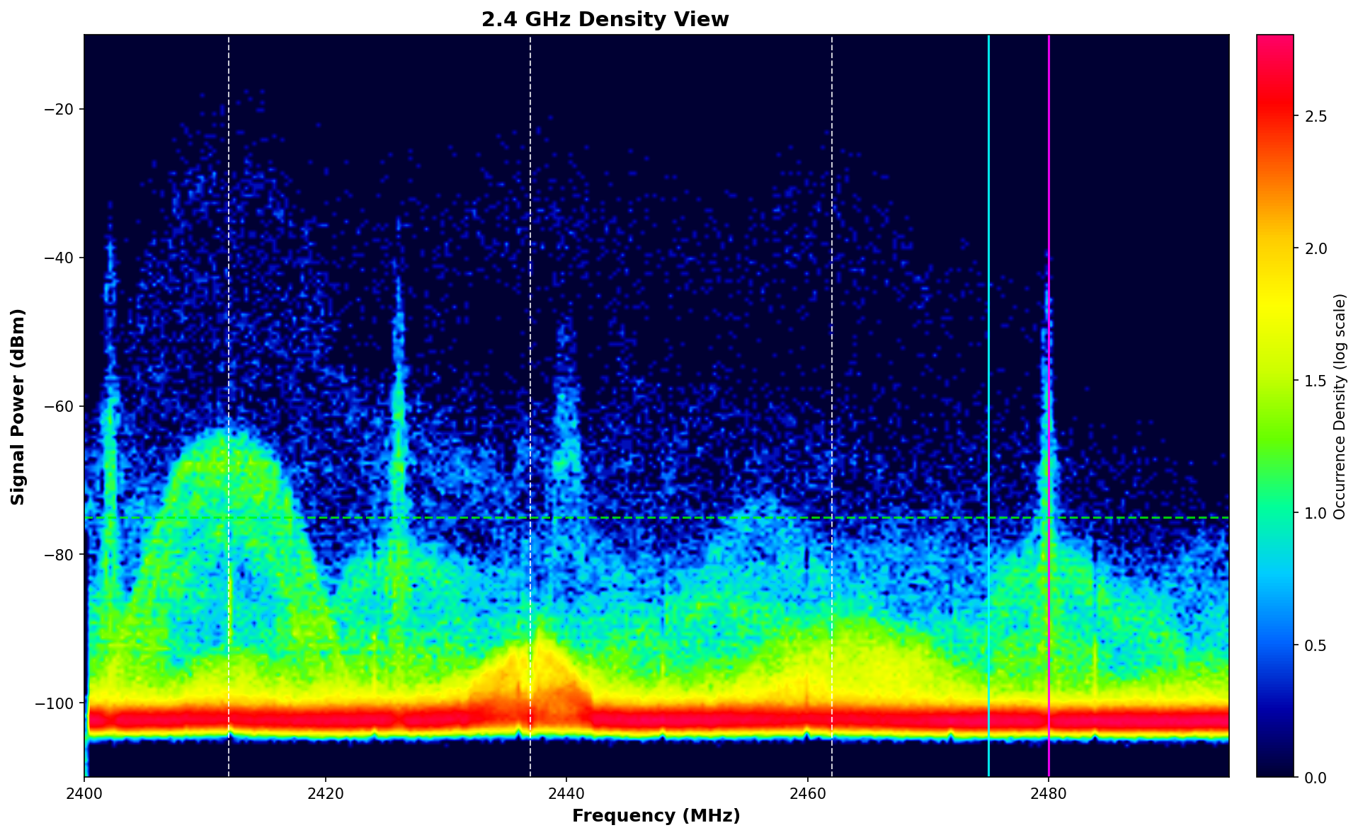
Density View from a real site survey. The colored “heat map” shows RF activity accumulated over time–warmer colors (red/yellow) indicate higher activity.
What You’re Seeing in This Density View #
The Density View accumulates RF data over time, building a “heat map” of spectrum usage:
X-Axis (horizontal): Frequency from 2.400 GHz (left) to 2.500 GHz (right)
Y-Axis (vertical): Signal strength in dBm (stronger signals appear higher)
Colors: Indicate how often that frequency/power combination occurred
Red/Orange = Very frequent activity (high congestion)
Yellow = Moderate activity
Blue/Green = Occasional activity (less congested)
Dark/Black = Little to no activity (ideal for Zigbee)
Look for: The “humps” are Wi-Fi access points (~20 MHz wide each). The right edge of the spectrum (above 2.472 GHz) is where Zigbee channel 25 operates–ideally this area should be dark/quiet.
Reading the Density View #
Element | What It Shows | What to Look For |
|---|---|---|
X-Axis (Horizontal) | Frequency in GHz (2.400 – 2.500) | Identify which channels have activity |
Y-Axis (Vertical) | Signal strength in dBm (-100 to -20) | Higher values = stronger signals |
Red/Orange Areas | High RF activity (frequent, strong signals) | Avoid placing Zigbee in these frequencies |
Yellow Areas | Moderate RF activity | Acceptable for Zigbee routers; not ideal for end devices |
Blue/Green Areas | Low RF activity (infrequent signals) | Best locations for Zigbee channels |
Horizontal Bands | Continuous interference at specific frequencies | Non-Wi-Fi sources: wireless video, cameras, etc. |
“Humps” (20-22 MHz wide) | Wi-Fi access points | Note which Wi-Fi channels are in use |
The Waterfall View #
The Waterfall View shows real-time spectrum activity, with time flowing downward. Use it to see interference as it happens and identify patterns.
Real Wi-Spy Scan: Waterfall View
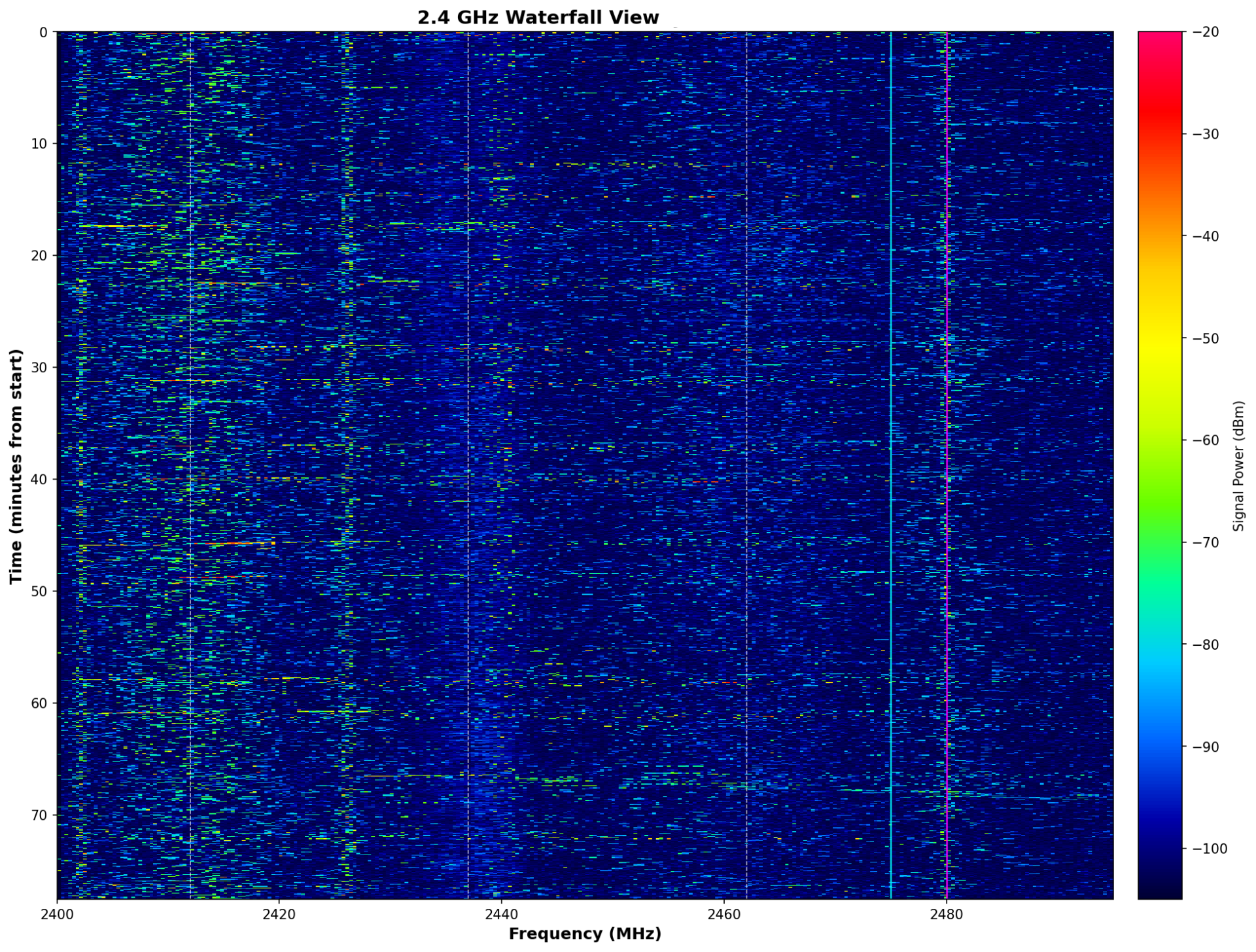
Waterfall View from a real site survey. Time flows downward–the top shows current activity, older data scrolls down.
What You’re Seeing in This Waterfall View #
The Waterfall displays spectrum activity in real-time, creating a scrolling history:
X-Axis (horizontal): Frequency from 2.400 GHz (left) to 2.500 GHz (right)
Y-Axis (vertical): Time–newest activity at top, scrolling downward as time passes
Colors: Indicate signal strength at that moment
Bright/Warm colors = Strong signal detected
Dim/Cool colors = Weaker signals
Dark/Black = No signal (quiet)
Key patterns to identify:
Vertical bands: Continuous signals at fixed frequencies (Wi-Fi APs, constant transmitters)
Horizontal streaks: Wideband bursts across multiple frequencies (microwave ovens, motors)
Intermittent blips: Periodic or occasional interference (Bluetooth, scheduled devices)
Dark vertical stripe on right edge: Clear spectrum for Zigbee channel 25
Reading the Waterfall View #
Element | What It Shows | What to Look For |
|---|---|---|
X-Axis (Horizontal) | Frequency in GHz | Match to Wi-Fi and Zigbee channel locations |
Y-Axis (Vertical) | Time (newest at top, scrolling down) | Watch for patterns: constant, periodic, or sporadic |
Bright Colors | Strong signals at that moment | Wi-Fi bursts, interference events |
Vertical Lines | Continuous signal at one frequency | Non-Wi-Fi interference (video transmitters, etc.) |
Horizontal Streaks | Wideband burst (across many frequencies) | Microwave oven, motor noise, electrical interference |
Sideband Lobes | Weaker signals extending beyond Wi-Fi channel | These can affect Zigbee channels that seem “outside” Wi-Fi |
WARNING: 🔎
Pro Tip: Finding Zigbee Channel 25
Zigbee channel 25 operates at 2.475-2.480 GHz. In the Density View, look at the right edge of the spectrum (above Wi-Fi channel 11). If this area is blue/green, channel 25 is a good choice. If you see red/orange activity there, investigate the source–it may be Wi-Fi channel 11 sideband interference or a non-Wi-Fi device.
Common Interference Signatures #
Visual Pattern | Likely Source | Recommended Action |
|---|---|---|
20 MHz humps on Ch 1, 6, 11 | Normal Wi-Fi APs | Select Zigbee channel to avoid overlap (Ch 25) |
Wide band (40-80 MHz) high power, periodic | Microwave oven | Relocate Helen 6+ ft from microwave path |
Narrow constant vertical line | Wireless video/HDMI transmitter | Identify in AV system; relocate or use wired |
Rapid hopping across entire spectrum | Bluetooth (FHSS) | Usually tolerable; note high-activity areas |
Multiple overlapping Wi-Fi humps | Dense environment / neighbor networks | Find clearest channel; may need channel coordination |
Noise floor elevated across entire band | USB 3.0 interference, LED lighting | Move Helen away from computers/USB hubs |
“A typical home environment showed lots of management overhead and ‘all too common bad channel planning on 2.4 GHz.’ When testing non-Wi-Fi interference, introducing non-Wi-Fi interference ‘killed the Wi-Fi on channels 1 through 6,’ and some APs immediately tried to broadcast on channel 11 as a result.”— MetaGeek
Generating Customer Reports #
Chanalyzer Report Builder generates professional PDF documentation suitable for customer delivery.
Report Contents #
Executive Summary: High-level findings and recommendations
Spectrum Captures: Visual evidence of RF environment
Network Inventory: All detected Wi-Fi networks with channels
Interference Analysis: Identified interference sources
Recommendations: Specific actions to improve Zigbee performance
Using Reports with Customers #
When presenting findings:
Show the data: “This is an objective measurement of your RF environment”
Identify interference: “These signals are competing with Zigbee for spectrum”
Explain the physics: “Wi-Fi transmits 10x stronger than Zigbee–when they overlap, Zigbee loses”
Provide solutions: “Moving to channel 25 and adding a router here will improve performance”
SUCCESS: ✅
Documentation Best Practice: Save .wsx session files and PDF reports for every complex installation. When callback issues arise, compare current spectrum to baseline to identify what changed.
Case Study: Luxury Residence with eero #
Environment #
3-story residence, 7,500 sq ft
24 Zigbee shades (mix of powered and Wirefree)
eero mesh Wi-Fi system with 6 access points
Reported Issue #
Customer reported random shade failures. Some shades worked reliably; others failed intermittently with no apparent pattern. Helen Diagnostics showed SILQ values fluctuating by 20-30 points between readings.
Wi-Spy Analysis Findings #
Finding | Impact |
|---|---|
eero using Wi-Fi channels 1, 6, AND 11 simultaneously | All three non-overlapping channels occupied |
Zigbee on default channel 20 | Direct overlap with Wi-Fi channel 6 |
Strong sideband interference from Ch 11 APs | Interference extending into Zigbee channel 24 |
Neighbor Wi-Fi visible on channels 1 and 6 | Additional congestion in lower spectrum |
Helen Coordinator located in AV rack | Metal obstruction and proximity to wireless HDMI |
Resolution Steps #
Changed Zigbee channel from 20 to 25 (above Wi-Fi traffic)
Added Zigbee Routers on 2nd and 3rd floors
Relocated Helen Coordinator from AV rack to open wall location
Re-paired problematic shades after mesh rebuild
Result #
SILQ values stabilized at 82+ for all shades. No further intermittent failures reported.
Long-Term Recommendation #
Documented that eero’s automatic channel selection prevents reliable RF coordination. For future stability, recommended migration to enterprise Wi-Fi with manual 2.4 GHz channel control. Provided Wi-Spy report for customer’s records.
Diagnostic Value: Without spectrum analysis, this issue would have appeared to be random hardware failure. The Wi-Spy data demonstrated that the problem was environmental–RF congestion–not product defect. This enabled the correct solution and avoided unnecessary hardware replacement.
Resources #
Professional Training #
CEDIA (Custom Electronic Design & Installation Association) provides professional certification for smart home integrators. The following certifications are relevant for Zigbee and wireless networking:
Certification | Focus Areas | Link |
|---|---|---|
RNS – Residential Networking Specialist | Network design, wireless configuration, RF environment analysis | |
IST – Integrated Systems Technician | Smart home installation fundamentals, system integration | |
CIT – Cabling & Infrastructure Technician | Structured cabling, infrastructure planning |
“Certified specialists have a working knowledge of the OSI model and can select and configure equipment to support residential projects of various sizes and complexity. They understand the nuances of environmental factors on wireless networks and can implement a range of advanced configuration techniques such as VLANS, QoS, and remote access to meet performance and security requirements.”— CEDIA RNS Certification
Technical References #
MetaGeek Documentation #
Silicon Labs / Connectivity Standards Alliance #
Industry Technical Guides #
Wi-Fi, Zigbee, and Thread Coexistence (Silicon Labs / Embedded Computing)
Zigbee Network Optimization Guide (Home Assistant Community)
Screen Innovations Support #
SI Help Center & AI Chatbot
Phone: 512-832-6939 (Option 3)
Recommended Equipment #
Spectrum Analysis Tools #
Product | Description | Link |
|---|---|---|
Wi-Spy Lucid | USB spectrum analyzer (2.4/5/6 GHz bands) | |
Chanalyzer 5 | Spectrum analysis software with report builder | |
Spectrum Bundle | Wi-Spy Lucid + Chanalyzer package |
Enterprise Wi-Fi Systems (Manual 2.4 GHz Channel Control) #
For professional installations requiring reliable Zigbee coexistence, recommend Wi-Fi systems with manual channel selection:
Vendor | Key Features | Typical Use Case |
|---|---|---|
Ubiquiti UniFi | Full channel control, software-defined, good value | Residential, small commercial |
Cisco Meraki | Cloud-managed, detailed RF analytics, auto-optimization | Enterprise, managed services |
Ruckus | Advanced RF management, high-density support | Hospitality, MDU, enterprise |
Aruba | AI-powered optimization, enterprise integration | Large enterprise, campus |
WARNING: ⚠️
Systems to Avoid for Professional Zigbee Installations: Consumer mesh Wi-Fi systems (eero, Google Wifi, Netgear Orbi) that do not allow manual 2.4 GHz channel selection. These systems automatically change channels, making RF coordination with Zigbee impossible.