
Before Proceeding #
WARNING: SI recommends conducting a visual inspection, using either Method 1 or Method 2, to check the internal brackets, material roll, and electronics for any concealed shipping damage before proceeding with the screen installation.
For best results, read the instructions in their entirety before proceeding with assembly. Actions contrary to the instructions invalidate the warranty and may result in serious damage and/or injury.
Preparing for Installation: #
It is crucial that all installations are planned out carefully before specifying a screen order and assembly.
Before installation, Bracket/Mounting method and Assembly Installation method must be identified.
Do not use a knife to cut foam or wrapping, as this may damage the shade including, but not limited to, the cassette, fabric tube, and material roll.
The tube may shift within the cassette during shipping; open the cassette with care.
Unpacking the box – lay cassette, fabric tube, and material roll on a soft, clean surface during the installation process.
When removing from the box, ensure the assembly is kept horizontal to prevent damage.
Screen Innovations recommends METHOD 2 (removal of the material roll before installation) when installing the Solo 3 screen for better control and safety of the material inside.
When removing material from the cassette, use at least two people to lay material down on a clean, flat surface, such as a blanket or sheet.
When utilizing either method, especially METHOD 1, make certain there are enough installers/hoisting equipment to safely lift the cassette (and/or material) onto the brackets.
Brackets must be level and in-line with one another before attempting to lift cassette onto brackets. Use safe lifting and rigging techniques.
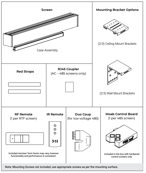
Parts in the Box #
Solo 3 675 External – Indoor #
Installation Steps #
575/675 External Mount Installation Guide #
The Solo 3 can also be mounted without removing the roll – skip to Step 3: Installing the Cassette.
If drilling through the cassette is required, the cassette must be square or the door will not line up, causing poor operation.
Electrical work should be performed following appropriate electrical codes and regulations by a licensed electrical professional.
Use fasteners appropriate for the structure the Solo 3 Screen will be mounted to.
Do not use any sharp blades when opening the packaging.
Step 1: Unpacking #
Starting with the cassette on a soft, clean surface, remove the screws from the fascia door and open to reveal the inside.
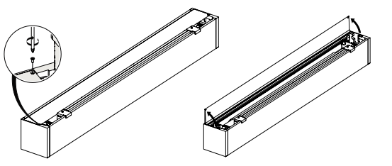
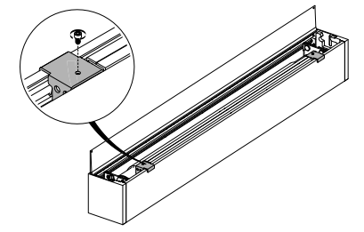
Remove both of the exposed red weight bar clips (2) by removing the attached screws from the 2 brackets.
Step 2: Material Roll Removal #
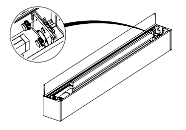
Undo the silver safety screws, then press the latch as shown.
Using the red straps, loop the straps under the material roll, being careful to avoid contact with the material or any obstructions.
With the help of the straps on both the ends, slowly pull out material roll and set it aside.
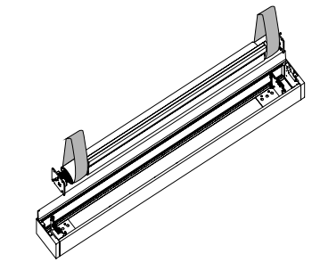
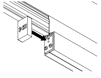
Remove the clips from the end of the weight bar, and attach the magnetic end caps.
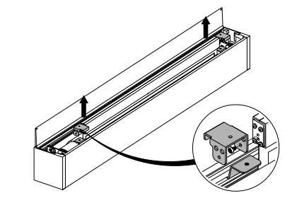
Step 3: Installing the Cassette #
Installation requires two or more people and/or hoisting equipment. Please use safe lifting and rigging techniques.
Wall Mount #
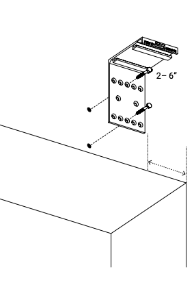
Ceiling Mount #
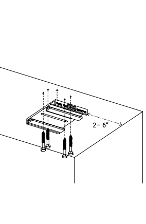
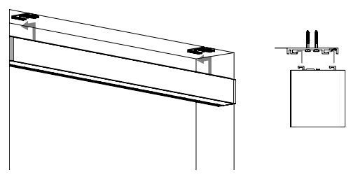
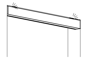
Lift and secure the cassette onto the brackets.
Once the bracket engages, the cassette will “click” into place.
Step 4: Re-Installing the Material Roll #
With the cassette mounted, open the door and slide the material roll with mounting plates on each end into the cassette.
Each end will “click” into place as the brackets engage.
The roll must remain level while installing into the cassette.
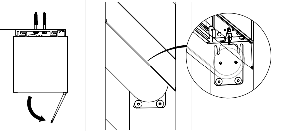
Fasten the silver safety screws on the mounting plates to secure the material roll.
Plug motor power cable into the barrel connector located in the cassette.
This step is required for safety. Back safety screws out before installation. Must be re-engaged after installing material roll.
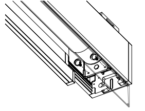
Step 5: Installing the Fascia Door #
To close the fascia door, set the door into the cassette; the door will hook in by gravity.
Secure with screws.
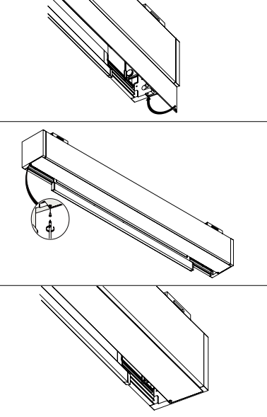
Step 6: MOAB and Wiring #
Inside Cassette Wiring – 24V DC #
Terminate the wires using the provided terminal block, shown below.
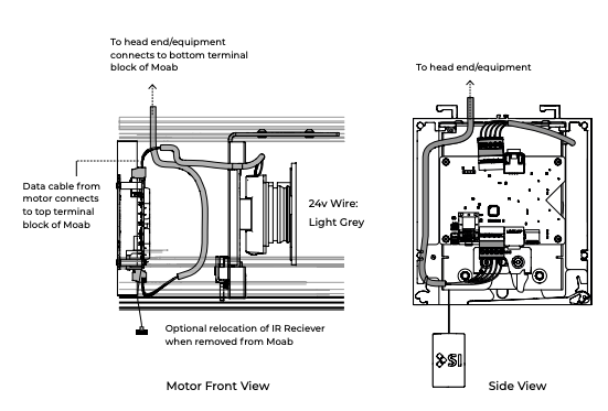
Detailed Low Voltage Power and 485 Control Wiring (DC Motor) #

Inside Cassette Wiring – 110V/220V AC #
Terminate the wires with the provided terminal block, as shown below.
Locate junction box appropriately.

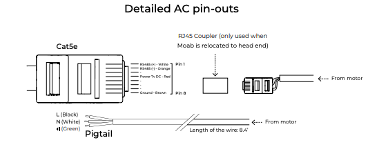
Screen Setup and Integration with MOAB #
See the MOAB Setup & Integration section below for complete setup instructions.