
MOAB Setup & Integration #
Connections and Pinouts #
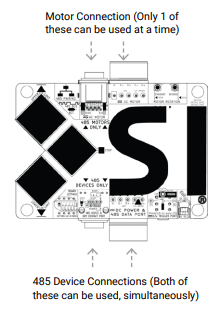
Motor Connections: #
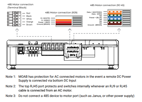
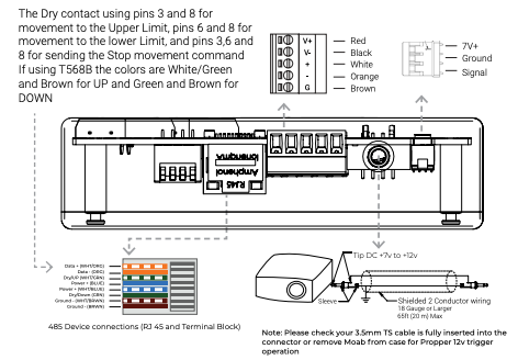
Bottom Connections: #
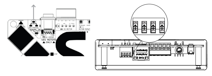
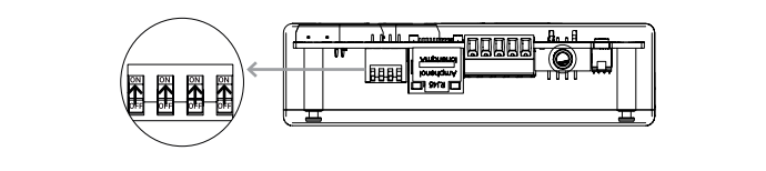
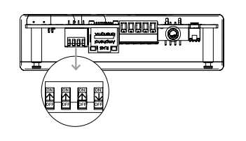
Dip Switches #
Tip: While looking at the dip switches, and the numbers upside-down, flipping the Dip Switch ON, would be flipping it UP, towards the Buttons/board.
Programming Mode = ON, User Mode = OFF
IR Sensor Enabled = ON, IR Sensor Disabled = OFF
MOAB LED’s ON = ON, MOAB LED’s OFF = OFF
Buttons Enabled = ON, MOAB buttons Disabled = OFF
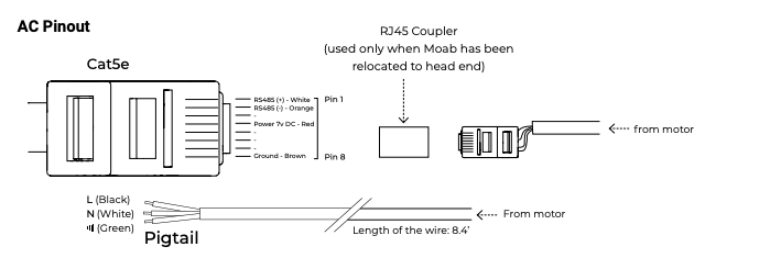
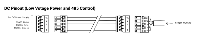
Pinouts #
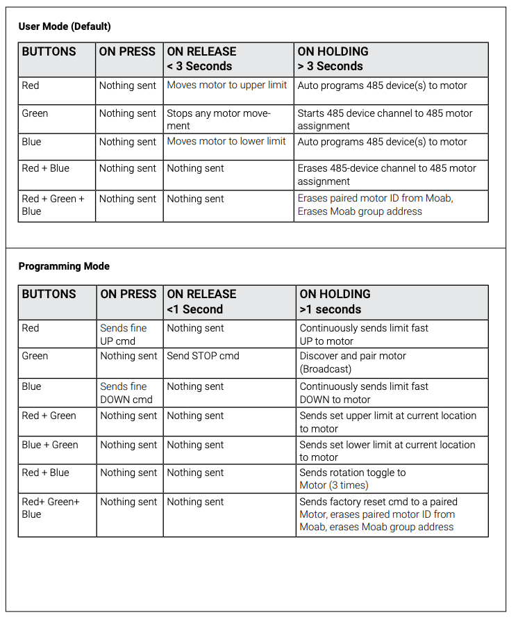
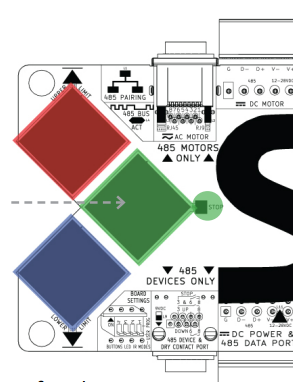
MOAB Button Details #
Basic Setup #
Factory Pairing: The Moab board should come pre-paired to the motor, with all limits already set.
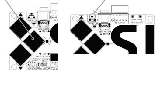
If the 485 Pairing LED (to the left of the RJ45 Motor Port) is OFF, the motor is paired.
If the LED is ON, pairing is required.
Step 1: Confirm or Pair the Motor #
Ensure all DIP switches are in the ON (up) position.
If pairing is required, press and hold the Green Button until the Green LED flashes and the 485 Pairing LED turns OFF.
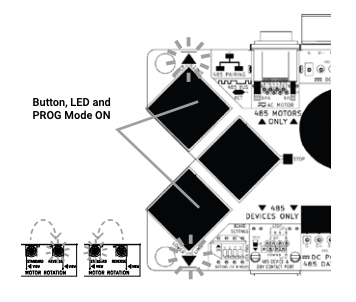
Step 2: Motor Rotation #
Motor rotation is factory-set. To adjust:
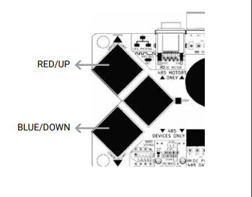
Hold the UP (Red) and DOWN (Blue) buttons for one second.
Test rotation by using small movements with the UP (Red) and DOWN (Blue) buttons.
If the motor rotation LED does not change or both LEDs are off, a reset or repair may be required.
Step 3: Setting Limits #
Ensure all DIP switches are in the ON position.
Upper Limit:
Use the RED/UP and BLUE/DOWN buttons to position the screen at the desired upper limit.
Press and hold both the RED and GREEN buttons until their LEDs flash. Release to save the upper limit.
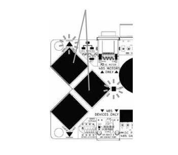
Lower Limit:
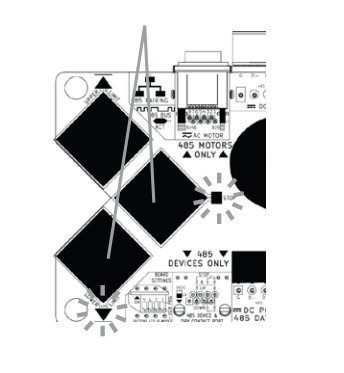
Use the RED/UP and BLUE/DOWN buttons to position the screen at the desired lower limit.
Press and hold both the BLUE and GREEN buttons until their LEDs flash. Release to save the lower limit.
Step 4: Switching to User Mode #
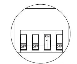
Move Dip Switch #1 into the OFF position.
In User Mode:
A single press on RED/UP will move the screen to the upper limit.
A single press on BLUE/DOWN will move the screen to the lower limit.
Controlling via IR #
Before controlling your screen, make sure your limits are set and the MOAB is in User Mode
Dip Switch #2 in the ON position allows the IR Receiver to be active.
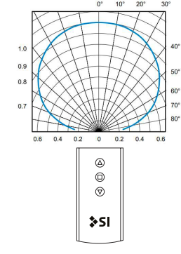
State-of-the-art built-in infrared sensor
Internal DSP filtering for PCM to improved accuracy
Improved immunity against ambient light and FL lighting
Improved directivity with ultra wide IR reception
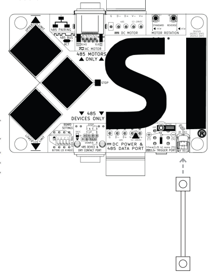
You may also remove the IR Sensor from the PCB board and extend it for placement in the slot under the screen with included extension cable.
Locate the slot on the right side just above the Din Rail feature, using a large flathead screw driver, gently pry the bottom away from the top. Unplug the IR cable to remove the IR Receiver from PCB, place your thumb over the IR Receiver and forefinger over the rear connector and gently move the IR Receiver back and forth a few times until it breaks away from the PCB. Now reconnect the IR Receiver with the included extension cable.
IR Hex Codes #
UP:
0000 006c 0000 000c 0006 011b 0006 011b 0006 00bb 0006 00bb 0006 00bb 0006 00bb 0006 00bb 0006 00bb 0006 00bb 0006 00bb 0006 011b 0006 08a4
STOP:
0000 006c 0000 000c 0006 011b 0006 011b 0006 00bb 0006 00bb 0006 00bb 0006 00bb 0006 00bb 0006 00bb 0006 00bb 0006 011b 0006 011b 0006 08a4
DOWN:
0000 006c 0000 000c 0006 011b 0006 011b 0006 00bb 0006 00bb 0006 00bb 0006 00bb 0006 00bb 0006 00bb 0006 00bb 0006 011b 0006 00bb 0006 08a4
Controlling via 12v Trigger #
Before controlling your screen, make sure your limits are set and the MOAB is in User Mode
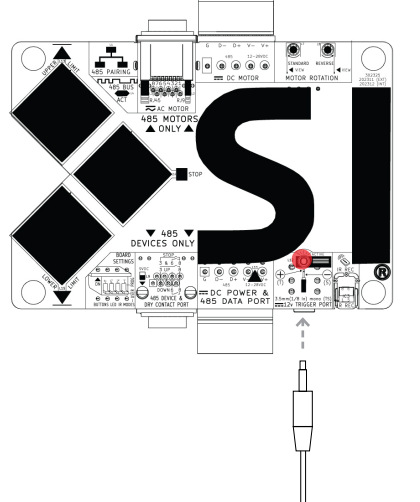
Use a 3.5mm (1/4″) mono TS phone jack to connect to the 3.5mm port on the bottom of the Moab board.
The 12v DC trigger is a latched continuous control signal.
When a voltage from 7-12v DC is applied on this port, Moab will turn on the active LED and send a 485 command to the motor. This will move the motor to the lower limit if connected and power applied.
When this same voltage is removed from the port, Moab sends a 485 command to the motor. This moves the paired motor to the upper limit if connected and power applied.
Controlling via Contact Closure #
Before controlling your screen, make sure your limits are set and the MOAB is in User Mode
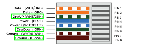
Use the bottom RJ45 Black Port for the momentary dry contact using pins 3 and 8 for movement to the Upper Limit, pins 6 and 8 for movement to the lower Limit, and pins 3, 6 and 8 for sending the Stop movement command. If using T568B the colors are White/Green and Brown for UP and Green and Brown for DOWN.
RS485 Keypad Pairing and Programming #
Before controlling your screen, make sure your limits are set and the MOAB is in User Mode
Connect the Keypad to the MOAB:
Plug the RJ45 from the Keypad to the bottom RJ45 of the MOAB
Make sure the Dip Switch #1 is OFF/User Mode
Press and Hold the Blue OR Red button until the corresponding LED begins to blink
The Red Pairing LED and the Green ACT LED will flash, wait until this finishes blinking before moving to the next step
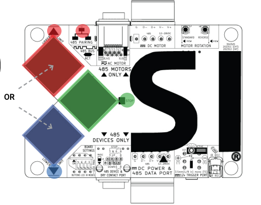
Now, push and Hold the Green button until the corresponding LED begins to blink, and the Red 485 Pairing LED and Green ACT LED will begin flashing
WARNING: You will now have 10 seconds to perform the next step
Next, press the Group or Preset number you wish to program, then press the STOP button on the keypad, and the LED’s will stop flashing.
Factory Reset #
With the MOAB in User Mode:
Press and Hold the RED, GREEN and BLUE buttons together until the LED’s begin to blink.
This will un-pair the Motor from the MOAB and erase all groups.
Resetting the Motor via MOAB: #
With the MOAB in Programming Mode:
Press and Hold the RED, GREEN and BLUE buttons together until the LED’s begin to blink.
This will un-pair the Motor from the MOAB and erase all limits and motor rotation from the motor.